Self-repairing transformer oil conservator respirator

A technology of transformer oil and self-repair, which is applied in the field of transformers and can solve problems such as easy blockage

Inactive Publication Date: 2020-03-06
翟福喜
View PDF2 Cites 3 Cited by
  • Summary
  • Abstract
  • Description
  • Claims
  • Application Information

AI Technical Summary

Problems solved by technology

[0005] The purpose of the present invention is to provide a self-repairing transformer oil conservator respirator that can be automatically repaired and is not easy to be blocked in view of the above-mentioned problems that require regular maintenance and are easy to be blocked.

Method used


Image

  • Self-repairing transformer oil conservator respirator
  • Self-repairing transformer oil conservator respirator
  • Self-repairing transformer oil conservator respirator

Examples


Embodiment 1

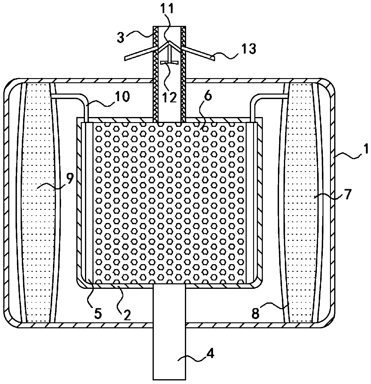
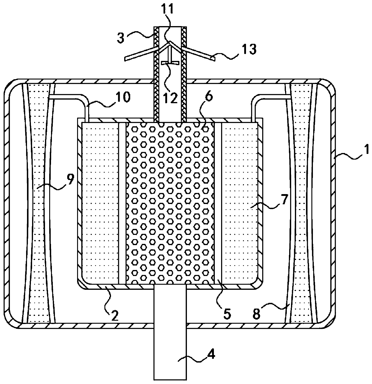
[0018] Such as Figure 1-2 As shown, a self-repairing transformer oil pillow respirator includes an outer shell 1 and an inner shell 2, the outer shell 1 and the inner shell 2 are made of light-transmitting materials, such as PVC materials, and the outer shell 1 is set on The inner shell 2 is fixedly connected with the inner shell 2, the upper end and the lower end of the inner shell 2 are fixedly connected with an upper air guide tube 3 and a lower air guide tube 4 respectively, the upper end of the upper air guide tube 3 communicates with the outside world, and the lower air guide tube 4 The lower end of the upper air duct 3 is connected with the transformer oil conservator, and the inner wall of the upper air duct 3 is rotatably connected with a dust filter 11, and the lower surface of the dust filter 11 is fixedly connected with a fan 12, and the fan 12 is coaxially arranged with the upper air duct 3, and the dust filter 11 is in the form of The center is arranged in an um...

Embodiment 2

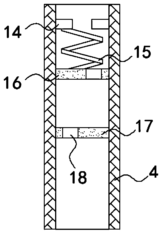
[0025] Such as image 3 As shown, the difference between this embodiment and Embodiment 1 is that the inner side wall of the lower air duct 4 is fixedly connected with a limit ring 14, and the lower end of the limit ring 14 is fixedly connected with an upper sealing plate 16 through a memory spring 15, and the upper end of the limit ring 14 is fixedly connected with an upper sealing plate 16. The bottom of the sealing plate 16 is provided with a lower sealing plate 17, the lower sealing plate 17 is fixedly connected with the inner side wall of the lower air guide tube 4, and the upper sealing plate 16 and the lower sealing plate 17 are all provided with vent holes 18, and the two vent holes 18 are staggered. set up.

[0026] In this embodiment, when the lens gathers light, the temperature in the inner casing 2 rises, and the memory spring 15 stretches to make the two sealing plates contact each other, and then the lower air duct 4 is closed to make the moisture evaporated in t...


PUM


Abstract

The invention belongs to the field of transformers, and particularly relates to a self-repairing transformer oil conservator respirator, comprising an outer shell and an inner shell, wherein the outershell is disposed outside the inner shell and fixedly connected to the inner shell; the upper end and the lower end of the inner shell fixedly communicate with an upper air duct and a lower air duct,respectively; the upper end of the upper air duct is in communication with the outside; the lower end of the lower air duct is in communication with a transformer oil conservator; two transparent plates are in sealed and sliding connection to the inner side wall of the inner shell; a gap between the two transparent plates is filled with silica gel; gaps between the surfaces of the two transparentplates away from each other and the inner side wall of the inner shell are filled with a sucrose solution; multiple groups of lenses are disposed in the outer shell; the groups of lenses are arrangedoutside the inner shell in a circular array; and each group of lenses includes two light-transmitting plates arranged in parallel with each other. The self-repairing transformer oil conservator respirator can automatically evaporate the moisture in the saturated silica gel by light, can be reused without manual periodic maintenance. A dust filter can filter out the dust in the air to avoid blocking the silica gel.

Description

technical field [0001] The invention belongs to the field of transformers, in particular to a self-repairing transformer oil conservator respirator. Background technique [0002] When the volume of transformer oil expands or decreases with the temperature of the oil, the oil conservator plays the role of regulating the oil volume and ensuring that the transformer oil tank is always filled with oil. Filter and absorb water, slow down the oxidation and damp speed of transformer oil in the oil conservator. [0003] Most traditional oil pillow respirators use silica gel as a water absorbent. Silica gel can absorb the moisture in the air entering and leaving the oil pillow. When the moisture in the silica gel is saturated, the silica gel needs to be taken out and heated at 120°C to absorb the moisture in the silica gel. and impurities are released, and then put into the respirator for reuse. Therefore, the existing transformer needs regular maintenance and inspection, which is v...

Claims


Application Information

Patent Timeline
Patent Type & Authority Applications(China)
IPC IPC(8): H01F27/14B01D46/10B01D46/00B01D53/28
CPCH01F27/14B01D46/103B01D46/0056B01D53/28B01D2257/80
Inventor 翟福喜
Owner 翟福喜
Why Eureka
Try Eureka