C-PVC power cable protection pipe

A technology for power cables and protection tubes, applied in the field of C-PVC power cable protection tubes, can solve the problems of weak protection of power cables, no adjustment function, and low fire performance, so as to improve protection ability, enhance stability, The effect of improving versatility

Inactive Publication Date: 2020-03-06
江苏天菱电力设备有限公司
View PDF11 Cites 8 Cited by
  • Summary
  • Abstract
  • Description
  • Claims
  • Application Information

AI Technical Summary

Problems solved by technology

[0003] The purpose of the present invention is to overcome the existing problems of the existing C-PVC power cable protection tubes that have no adjustment function, low versatility, low fire performance, and weak protection for power cables, and provide a reasonable structural design, C-PVC power cable protection tube with convenient adjustment, good versatility, good fire resistance, and high protection for power cables

Method used


Image

  • C-PVC power cable protection pipe
  • C-PVC power cable protection pipe
  • C-PVC power cable protection pipe

Examples


Embodiment 1

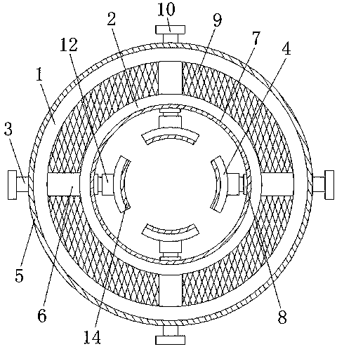
[0020] as attached Figure 1-3 As shown, a C-PVC power cable protection tube includes an outer ring 1, an inner ring 2, an adjusting screw 3 and a fastening block 4, and it is characterized in that: the outer ring 1 is provided with a connecting screw barrel 6, so The inner ring 2 described above is arranged in the outer ring 1, the outer wall of the inner ring 2 is connected with the connecting screw barrel 6, and the inner wall of the inner ring 2 is provided with a fixing nut 8 communicating with the connecting screw barrel 6, and the outer ring 1 is connected with the connecting screw barrel 6. The screw barrel 6, the inner ring 2 and the connecting screw barrel 6 are connected by welding to enhance the connection strength between the outer ring 1 and the connecting screw barrel 6 and the inner ring 2 and the connecting screw barrel 6, and improve the structural strength of the power cable protection tube , enhance the protection of the power cable protection tube to the p...

Embodiment 2

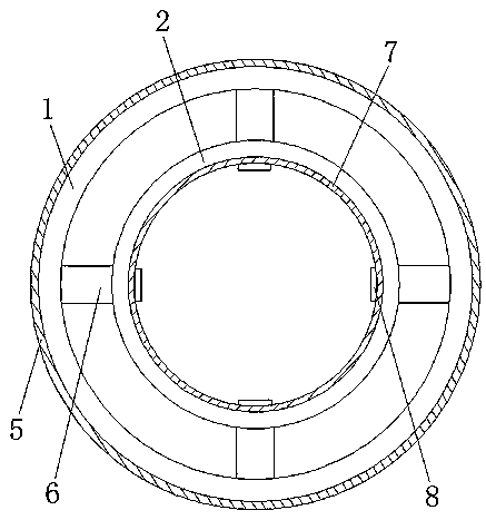
[0028] as attached Figure 4 As shown, a C-PVC power cable protection tube includes an outer ring 1, an inner ring 2, an adjusting screw 3 and a fastening block 4, and it is characterized in that: the outer ring 1 is provided with a connecting screw barrel 6, so The inner ring 2 described above is arranged in the outer ring 1, the outer wall of the inner ring 2 is connected with the connecting screw barrel 6, and the inner wall of the inner ring 2 is provided with a fixing nut 8 communicating with the connecting screw barrel 6, and the outer ring 1 is connected with the connecting screw barrel 6. The screw barrel 6, the inner ring 2 and the connecting screw barrel 6 are connected by welding to enhance the connection strength between the outer ring 1 and the connecting screw barrel 6 and the inner ring 2 and the connecting screw barrel 6, and improve the structural strength of the power cable protection tube , enhance the protection of the power cable protection tube to the pow...


PUM


Abstract

The invention discloses a C-PVC power cable protection pipe. The C-PVC power cable protection pipe comprises an outer ring, an inner ring, adjusting screw rods and fastening blocks; the C-PVC power cable protection pipe is characterized in that a connecting screw cylinder is arranged in the outer ring; the inner ring is arranged in the outer ring; the outer wall of the inner ring is connected withthe connecting screw cylinder; the inner wall of the inner ring is provided with fixing nuts communicated with the connecting screw cylinder, the adjusting screw rods penetrate into the connecting screw cylinder from the outer ring and penetrate out of the connecting screw cylinder and the fixing nuts, one end of each adjusting screw rod in the inner ring is provided with a clamping ring, each fastening block is provided with an installation ring, and each installation ring is connected with an adjusting screw rod. The distance between the fastening blocks can be adjusted through the adjusting screw rods; therefore, the distance between the fastening blocks can be adjusted according to the power cables of different sizes, the protection pipe can be suitable for power cables of different sizes, the universality of the power cable protection pipe is improved, and the application range of the power cable protection pipe is expanded.

Description

technical field [0001] The invention relates to the technical field of cable protection tubes, in particular to a C-PVC power cable protection tube. Background technique [0002] C-PVC power cable protection tube is mainly made of C-PVC resin with excellent heat resistance and insulation performance. C-PVC products are currently recognized as green and environmentally friendly products. Its excellent physical and chemical properties are being paid more and more attention by the industry. However, The existing C-PVC power cable protection tubes generally have a simple structure and do not have an adjustment function, so it is impossible to pressurize the built-in storage power cables. Secondly, the power cable protection tubes have low fire performance and are not strong enough to protect the power cables. high. Contents of the invention [0003] The purpose of the present invention is to overcome the existing problems of the existing C-PVC power cable protection tubes tha...

Claims


Application Information

Patent Timeline
Patent Type & Authority Applications(China)
IPC IPC(8): H02G3/04H02G9/04H02G9/06H02G3/03B32B1/08B32B33/00
CPCB32B1/08B32B33/00B32B2307/3065B32B2307/554H02G3/03H02G3/04H02G3/0412H02G9/04H02G9/06
Inventor 刘茜茜
Owner 江苏天菱电力设备有限公司
Why Eureka
Try Eureka