Dry powder spray feeding system and lifting fire truck

A technology of dry powder and dry powder tank, which is applied in fire rescue and other directions, can solve the problems of high spraying pressure and insufficient pressure, and achieve the effects of avoiding the reduction of conveying speed, improving powder output efficiency, and ensuring spraying speed

Pending Publication Date: 2020-03-10
XCMG CONSTR MACHINERY +1
View PDF0 Cites 1 Cited by
  • Summary
  • Abstract
  • Description
  • Claims
  • Application Information

AI Technical Summary

Problems solved by technology

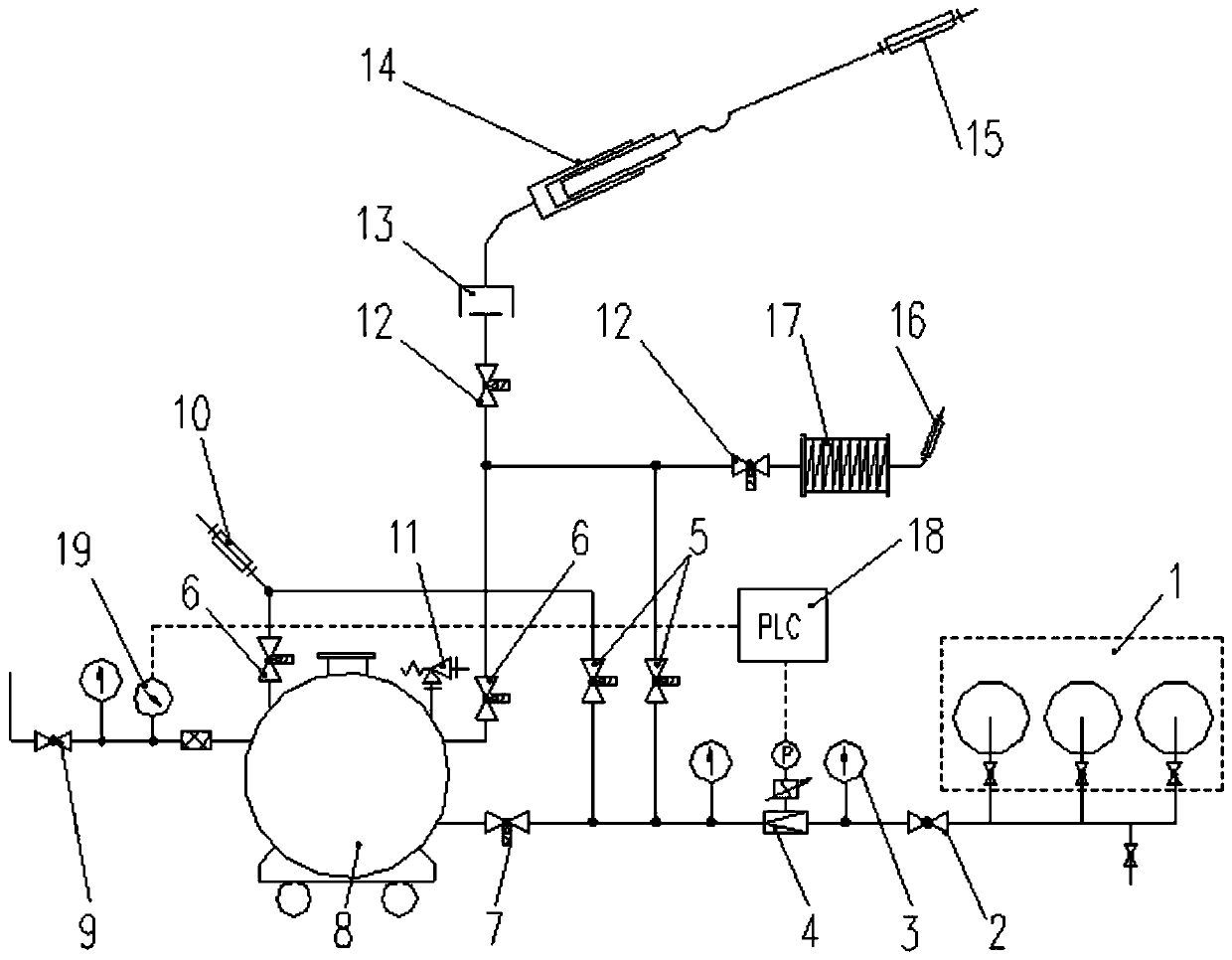
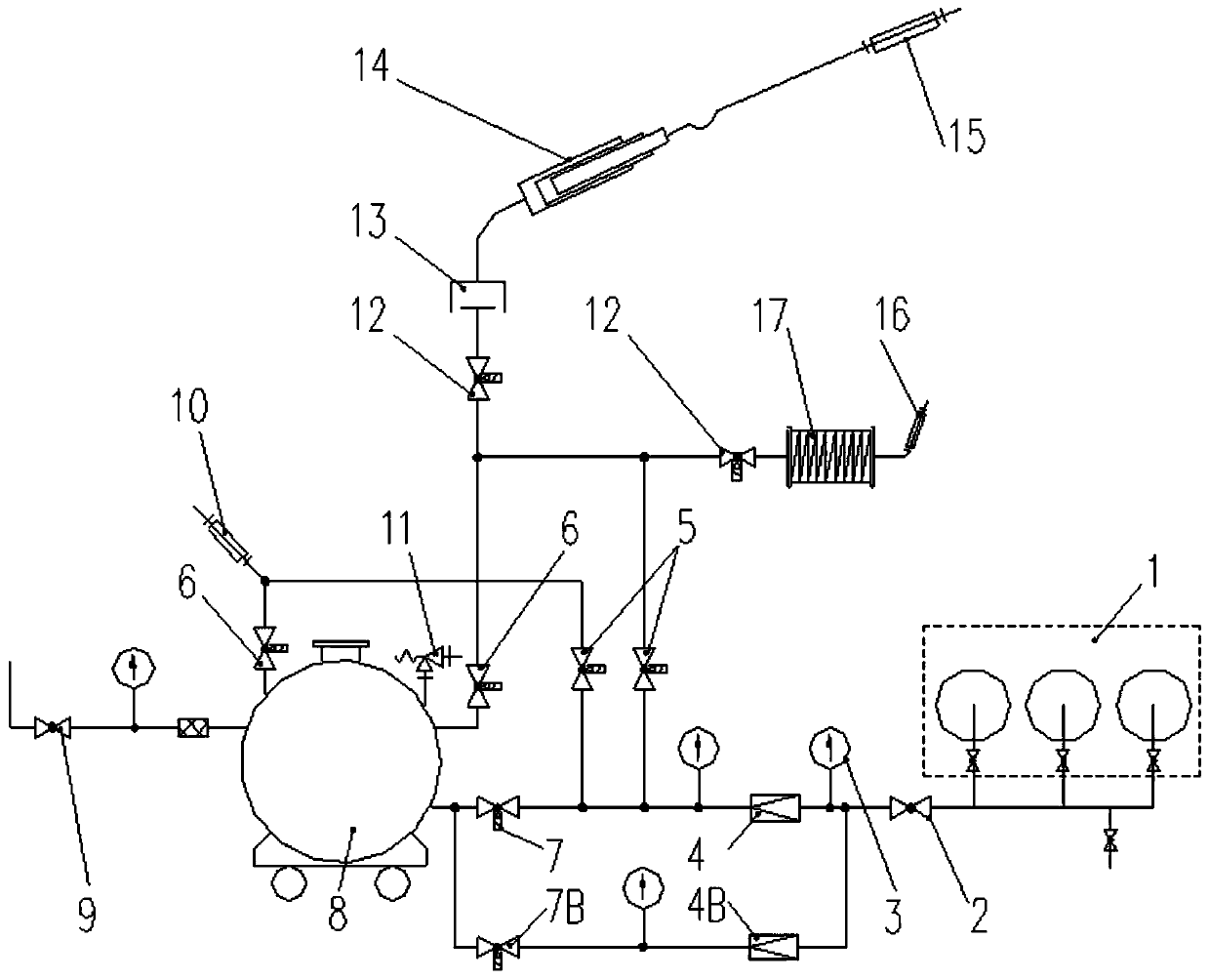
[0009] In view of this, the embodiment of the present disclosure provides a dry powder spraying system, which can keep the blowing pressure of the dry powder tank stable during the spraying process, and solve the problem that the existing dry powder spraying system is prone to accidents in the later stage of spraying due to reduced pressure spraying. The problem of insufficient high injection pressure

Method used


Image

  • Dry powder spray feeding system and lifting fire truck
  • Dry powder spray feeding system and lifting fire truck

Examples


Embodiment Construction

[0054] Various exemplary embodiments of the present disclosure will now be described in detail with reference to the accompanying drawings. The description of the exemplary embodiments is merely illustrative, and in no way serves as any limitation to the present disclosure and its application or use. The present disclosure can be implemented in many different forms and is not limited to the embodiments herein. These embodiments are provided to make the present disclosure thorough and complete, and to fully express the scope of the present disclosure to those skilled in the art. It should be noted that unless specifically stated otherwise, the relative arrangement of components and steps, material components, numerical expressions and numerical values ​​set forth in these embodiments should be interpreted as merely exemplary rather than limiting.

[0055] The "first", "second" and similar words used in the present disclosure do not indicate any order, quantity or importance, but ...


PUM


Abstract

The invention relates to a dry powder spray feeding system. The dry powder spray feeding system comprises a high pressure air source, a dry powder pot, a dry powder ejector, a first decompressing valve and a flow equilibrium assembly, wherein the dry powder pot comprises an air inlet opening and a power outlet opening, and the air inlet opening communicates with the high pressure air source; the dry powder ejector communicates with the powder outlet opening; the first decompressing valve is connected between the air inlet opening and the high pressure air source; and the flow equilibrium assembly is placed between the high pressure air source and the dry powder pot, and can enable the flow of air flowing through the air inlet opening and the powder outlet opening to be the same by controlling the air inlet amount from the high pressure air source to the dry powder pot. Therefore, according to the dry powder spray feeding system provided by the embodiment of the application, spraying and sending pressure of the dry powder pot can be maintained to be stable in the spraying process, and the difficult problem that a conventional dry powder spray feeing system is easy to cause underpressure for lifting spray feeding at the later-stage spray feeding caused by pressure-reduced spray feeing, can be solved.

Description

Technical field [0001] The present disclosure relates to the field of fire fighting devices, and in particular to a dry powder spraying system and a raised fire truck. Background technique [0002] The dry powder spraying system is a working device that uses inert gas such as nitrogen as the driving gas to fluidize the dry powder stored in the dry powder tank, and send it to the dry powder gun or dry powder gun through the transportation pipeline, and the working device is finally sprayed by the dry powder gun or dry powder gun The main working process includes the following steps: ①Inflate the dry powder tank from the high-pressure gas cylinder, and fluidize the dry powder in the dry powder tank under the set pressure; ②Open the dry powder outlet valve to make the dry powder-nitrogen two-phase flow Enter the transportation pipeline; ③ Supply the dry powder-nitrogen two-phase flow to the dry powder injector to spray out and inject it into the place that needs to be extinguished. ...

Claims


Application Information

Patent Timeline
IPC IPC(8): A62C27/00A62C31/00A62C37/40
CPCA62C27/00A62C31/005A62C37/40A62C31/00A62C35/02
Inventor 田志坚李前进赵阳光樊艳阳
Owner XCMG CONSTR MACHINERY
Why Eureka
Try Eureka