Storage tank oil gas treatment device based on liquid nitrogen condensation and oil gas treatment method

A technology for oil and gas treatment and liquid nitrogen storage tanks, which is applied in gas treatment, separation methods, chemical instruments and methods, etc., can solve the problems of uncontrolled oil and gas escape, casualties, violations, etc. Prevent safety accidents and realize the effect of environmentally friendly discharge

Inactive Publication Date: 2020-03-10
CHINA PETROLEUM & CHEM CORP +1
View PDF4 Cites 3 Cited by
  • Summary
  • Abstract
  • Description
  • Claims
  • Application Information

AI Technical Summary

Problems solved by technology

[0004] Therefore, during the cleaning process of the storage tank, the volatilized oil and gas in the storage tank will enter the air, encountering static electricity and electric sparks will cause disasters such as fire and explosion, which seriously affects the personal safety and health of residents around the gas station. It violates the relevant provisions of the existing national environmental protection laws and regulations, and is no longer suitable for the requirements of modern operations
In recent years, there have been many safety production accidents in China where oil and gas flash explosions caused casualties due to uncontrolled escape of oil and gas during tank cleaning

Method used


Image

  • Storage tank oil gas treatment device based on liquid nitrogen condensation and oil gas treatment method

Examples


Embodiment 1

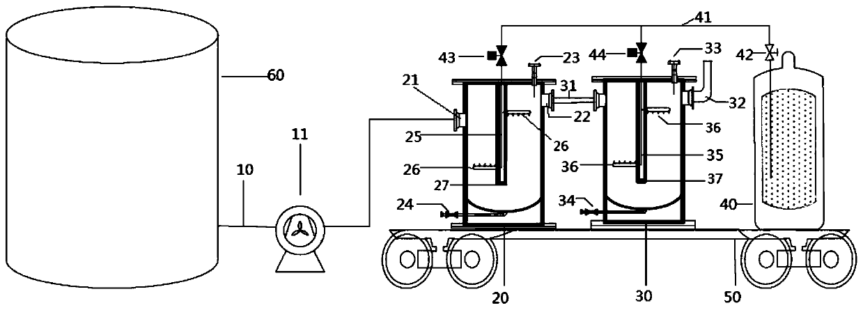
[0073] Such as figure 1 As shown, the oil and gas treatment device includes a suction pipe 10 , a first condensation tank 20 , a second condensation tank 30 and a liquid nitrogen storage tank 40 connected in sequence.

[0074] A fan 11 is arranged on the suction pipe 10 .

[0075] The first condensation tank 20 is provided with an oil-gas inlet 21 and an oil-gas outlet 22, the oil-gas inlet 21 and the oil-gas outlet 22 are all arranged on the top of the first condensation tank 20, the oil-gas inlet 21 is connected with the suction pipe 10, and the oil-gas outlet 22 passes through The gas delivery pipe 31 communicates with the second condensation tank 30 . The inside of the first condensing tank 20 is provided with a hollow first baffle 27, the left bottom of the first baffle 27 is provided with a first shower 26, and the upper right side of the first baffle 27 is provided with another A first shower 26.

[0076] The structure of the second condensation tank 30 is exactly th...

Embodiment 2

[0085] The oil and gas treatment device adopts the same structure as that of Example 1.

[0086] However, during the condensation process, the temperature in the first condensation tank 20 is maintained at minus 4°C, and the temperature in the second condensation tank 30 is maintained at minus 85°C.

[0087] Based on the above oil and gas treatment device and under the above operating conditions, when the oil and gas concentration at the oil and gas inlet 21 is 40% VOL, the oil and gas concentration at the exhaust pipe 32 is 42% LEL, and the oil and gas treatment efficiency is 98.7%.

Embodiment 3

[0089] The oil and gas treatment device adopts the same structure as that of Example 1.

[0090] However, during the condensation process, the temperature in the first condensation tank 20 is maintained at minus 5°C, and the temperature in the second condensation tank 30 is maintained at minus 90°C.

[0091] Based on the above oil and gas treatment device and under the above operating conditions, when the oil and gas concentration at the oil and gas inlet 21 is 40% VOL, the oil and gas concentration at the exhaust pipe 32 is 33% LEL, and the oil and gas treatment efficiency is 99%.


PUM


Abstract

The invention relates to the technical field of oil gas treatment, and discloses a storage tank oil gas treatment device based on liquid nitrogen condensation and an oil gas treatment method. The device includes: a first condensation tank (20), in which a condensation structure is arranged, and on which an oil gas inlet (21) and an oil gas outlet (22) are formed; a second condensation tank (30), in which a second sprayer (36) is formed, wherein a gas feeding pipe (31) and a gas discharge pipe (32) are connected to the second condensation tank (30), the gas feeding pipe being connected to the oil gas outlet; and a liquid nitrogen storage tank (40) connected to a liquid nitrogen pipeline (41), wherein the second sprayer is connected to the nitrogen pipeline through a second feeding pipe (35). In the device, oil is condensed by multiple times through the first and the second condensation tanks in the oil gas treatment device, thereby purifying the oil gas and preventing uncontrolled escape. The device not only prevents safety accidents but also achieves environment-friendly discharge.

Description

technical field [0001] The invention relates to the technical field of oil and gas treatment, in particular to a storage tank oil and gas treatment device and an oil and gas treatment method based on liquid nitrogen condensation for treating oil and gas in cleaned oil and gas tanks. Background technique [0002] According to the regulations on the repair of oil storage tanks, the oil storage tanks need to be developed, inspected and repaired every 5-7 years of operation. At this time, the oil storage tanks need to be cleaned. Tank cleaning is to remove the sludge accumulated at the bottom of the tank and the condensed oil and wax on the tank wall. [0003] At present, the tank cleaning method used in China is mainly manual cleaning. Manual tank cleaning has problems such as high labor intensity, long construction period, poor safety, low crude oil recovery rate, and environmental pollution. The mechanical cleaning method is being promoted and applied in China. This cleaning...

Claims


Application Information

Patent Timeline
Patent Type & Authority Applications(China)
IPC IPC(8): B01D53/44B01D53/78
CPCB01D53/44B01D53/78B01D2251/2062B01D2257/708
Inventor 程龙军张健中陶彬王林王振中单晓雯尹树孟
Owner CHINA PETROLEUM & CHEM CORP
Why Eureka
Try Eureka