Oil gas treatment device and oil gas treatment method for oil gas tank based on liquid nitrogen condensation

A technology for oil and gas treatment and condensing tanks, which is applied in gas treatment, separation methods, chemical instruments and methods, etc., can solve the problems of uncontrolled oil and gas escape, fire and explosion, casualties, etc., to prevent the uncontrolled escape of oil and gas, prevent Safety accidents, the effect of realizing environmental protection discharge

Inactive Publication Date: 2020-03-10
CHINA PETROLEUM & CHEM CORP +1
View PDF11 Cites 0 Cited by
  • Summary
  • Abstract
  • Description
  • Claims
  • Application Information

AI Technical Summary

Problems solved by technology

[0004] Therefore, during the cleaning process of the gas station storage tank, the volatilized oil gas in the oil storage tank will enter the air, encountering static electricity and electric sparks will cause disasters such as fire and explosion, which seriously affects the personal safety and health of residents around the gas station. It is not healthy, and it also violates the relevant provisions of the existing national environmental protection laws and regulations, and is no longer suitable for the requirements of modern operations.
In recent years, there have been many safety production accidents in China where oil and gas flash explosions caused casualties due to uncontrolled escape of oil and gas during tank cleaning.

Method used


Image

  • Oil gas treatment device and oil gas treatment method for oil gas tank based on liquid nitrogen condensation

Examples


Embodiment 1

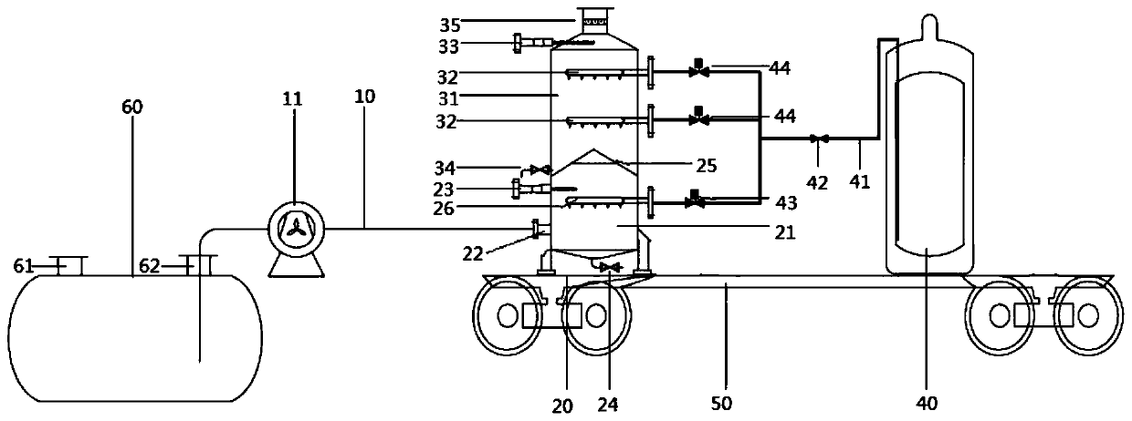
[0070] Such as figure 1 As shown, the oil and gas treatment device includes a suction pipe 10 , a condensation tank 20 and a liquid nitrogen storage tank 40 connected in sequence.

[0071] A fan 11 is arranged on the suction pipe 10 .

[0072] Condensation tank 20 comprises the oil gas inlet 22 that is arranged on the lower part of the side wall, the exhaust pipe 35 that is connected on the top wall and the grille hole plate 25 that is arranged inside, and described grille hole plate 25 is arranged on described oil gas along the height direction. between the inlet 22 and the exhaust port 35 , and divide the interior of the condensation tank 20 into a first condensation chamber 21 and a second condensation chamber 31 .

[0073] A first shower 26 is arranged inside the first condensation chamber 21, and two second showers 32 are arranged inside the second condensation chamber 31, and the first shower 26 and the second shower 32 pass through the first shower 26 respectively. Th...

Embodiment 2

[0081] The oil and gas treatment device adopts the same structure as that of Example 1.

[0082] However, during the condensation process, the temperature in the first condensation chamber 21 is maintained at minus 4°C, and the temperature in the second condensation chamber 31 is maintained at minus 85°C.

[0083] Based on the above oil and gas treatment device and under the above operating conditions, when the oil and gas concentration at the oil and gas inlet 22 is 50% VOL, the oil and gas concentration at the exhaust pipe 35 is 46% LEL, and the oil and gas treatment efficiency is 98.8%.

Embodiment 3

[0085] The oil and gas treatment device adopts the same structure as that of Example 1.

[0086] However, during the condensation process, the temperature in the first condensation chamber 21 is maintained at minus 5°C, and the temperature in the second condensation chamber 31 is maintained at minus 90°C.

[0087] Based on the above oil and gas treatment device and under the above operating conditions, when the oil and gas concentration at the oil and gas inlet 22 is 50% VOL, the oil and gas concentration at the exhaust pipe 35 is 41% LEL, and the oil and gas treatment efficiency is 99%.


PUM


Abstract

The invention relates to the technical field of oil gas treatment and discloses an oil gas treatment device and an oil gas treatment method for an oil gas tank based on liquid nitrogen condensation. The oil gas treatment device includes: a condensation tank (20) which includes an oil gas inlet (22), a gas discharge pipe (35) and a grating plate (25) that is disposed therebetween in height direction to separate the interior of the condensation tank (20) into a first condensation chamber (21) and a second condensation chamber (31), wherein a condensation structure is arranged inside the first condensation chamber and a second sprayer (32) is arranged in the second condensation chamber; and a liquid nitrogen storage tank (40) connected to a second feeding pipe via a liquid nitrogen pipeline (41). The oil gas successively passes through the first condensation chamber and the second condensation chamber, of which the temperatures are controlled to be different, so that the oil gas can be purified, thereby preventing uncontrolled escape and achieving environment-friendly emission.

Description

technical field [0001] The invention relates to the technical field of oil and gas treatment, in particular to an oil and gas tank oil and gas treatment device and an oil and gas treatment method based on liquid nitrogen condensation for treating oil and gas in cleaned oil and gas tanks. Background technique [0002] At present, China has more than 100,000 gas stations and about 400,000 buried oil storage tanks. According to the cleaning regulations of buried oil storage tanks, the oil storage tanks need to be cleaned every 3 to 5 years. When it is necessary to modify, overhaul or change the stored oil, it is also necessary to clean the oil storage tank. [0003] The cleaning of buried oil tanks in domestic gas stations mainly adopts manual cleaning. During the cleaning process, manual entry into the tank is required, which is poor in safety. At present, the cleaning of buried storage tanks at gas stations is currently being promoted and applied with mechanical tank cleanin...

Claims


Application Information

Patent Timeline
Patent Type & Authority Applications(China)
IPC IPC(8): B01D53/44B01D53/78
CPCB01D53/44B01D53/78B01D2251/2062B01D2257/708
Inventor 程龙军张卫华张健中单晓雯王振中尹树孟
Owner CHINA PETROLEUM & CHEM CORP
Why Eureka
Try Eureka