
Foamed plastic cutting machine

A technology of foam plastics and cutting machines, which is applied in the field of foam plastics, and can solve the problems of reduced cutting accuracy, excessive influence of processing time on the initial sharpness of the cutting position of the heating wire, and increased difficulty of processing operations, etc.

Active Publication Date: 2020-03-10
道县健恒环保科技有限公司
View PDF7 Cites 2 Cited by
  • Summary
  • Abstract
  • Description
  • Claims
  • Application Information

AI Technical Summary

Problems solved by technology

[0002] Foam plastics are widely used as a lightweight engineering material. The forming and processing methods of foam plastic products are generally carried out in the form of foam forming, splicing and cutting in the mold. Although the former adopts the method of molding and splicing The processing and manufacturing cost is reduced, but the difficulty of processing operation is increased, and the disadvantage of the latter using electric heating cutting is that the initial sharpness of the electric heating wire cutting position is greatly affected by the processing time. As the processing time prolongs, the electric heating wire The melted plastic residue in the wire cutting process will adhere to the heating wire, which will not only reduce the heating efficiency of the heating wire, but also reduce the cutting accuracy and even damage the cutting edge of the foam plastic. Based on the above premise, this case developed A styrofoam cutter to solve this problem

Method used


Image

  • Foamed plastic cutting machine
  • Foamed plastic cutting machine
  • Foamed plastic cutting machine

Examples


Embodiment

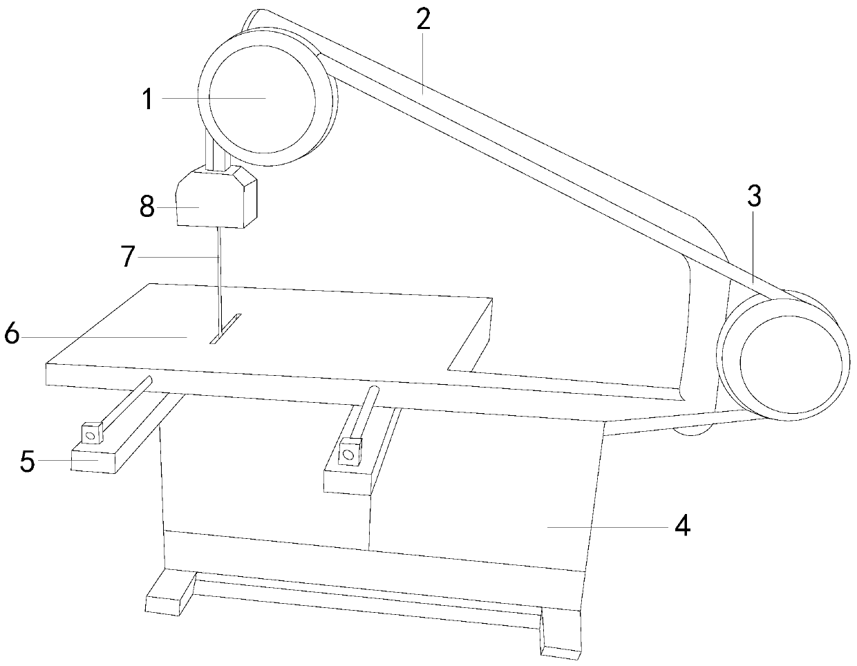
[0020] see figure 1, the present invention provides a cutting machine for foamed plastics, its structure includes: power shaft 1, bracket 2, transmission rod 3, body 4, adjustment seat 5, negative pressure plate 6, electric heating wire tube 7, self-cleaning cutter 8 , the power shaft 1 is located at both ends of the support 2 and connected to each other through the transmission rod 3, one end of the transmission rod 3 is connected to the fuselage 4, the side of the fuselage 4 is provided with an adjustment seat 5 and is located at the bottom of the negative pressure plate 6, the negative pressure The plate 6 runs through and connects the heating wire tube 7, and one end of the heating wire tube 7 is connected with the self-cleaning cutter 8, and the self-cleaning cutter 8 is connected with the power shaft 1. The interior is composed of rotating shaft parts, which mainly provide the source of power potential energy for other components of the equipment, and undertake the func...


PUM


Abstract

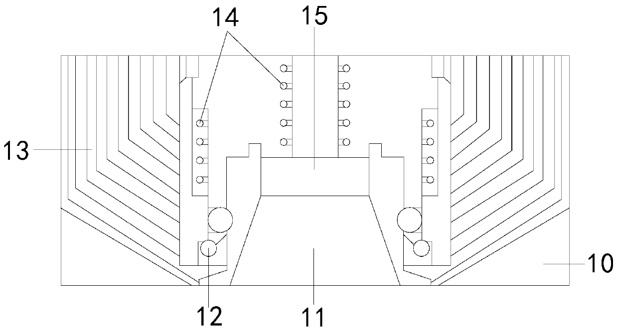
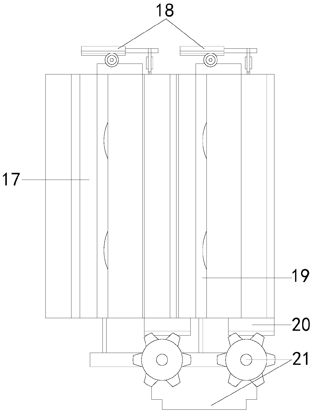
The invention discloses a foamed plastic cutting machine. The structure of the foamed plastic cutting machine comprises power shafts, a bracket, a transmission rod, a machine body, adjusting seats, anegative pressure plate, an electrothermal wire pipe and a self cleaning cutter, wherein the power shafts are arranged at two ends of the bracket, and are mutually connected with each other through the transmission rod. The foamed plastic cutting machine disclosed by the invention has the beneficial effects that a planning wheel seat is driven by the self cleaning cutter relying on the power provided by a conducting shaft and a power pipe to vertically extend downwards from a position at the topmost end of the electrothermal wire pipe to be mutually adhered to the electrothermal wire pipe, atthe same time, through the rotating acting force of the planning wheel seat, cleaning tooth blocks are embedded with the electrothermal wire pipe, and in the sliding downwards and rolling process, plastic defective materials produced on and adhered to the electrothermal wire pipe are planned and scraped; and after the plastic defective materials are scraped, the planning wheel seat can be voluntarily reset relying on a spring rod of the power pipe, so that the situation that subsequent operations are influenced is avoided.

Description

technical field [0001] The invention relates to the field of foamed plastics, in particular to a cutting machine for foamed plastics. Background technique [0002] Foam plastics are widely used as a lightweight engineering material. The forming and processing methods of foam plastic products are generally carried out in the form of foam forming, splicing and cutting in the mold. Although the former adopts the method of molding and splicing The processing and manufacturing cost is reduced, but the difficulty of processing operation is increased, and the disadvantage of the latter using electric heating cutting is that the initial sharpness of the electric heating wire cutting position is greatly affected by the processing time. As the processing time prolongs, the electric heating wire The melted plastic residue in the wire cutting process will adhere to the heating wire, which will not only reduce the heating efficiency of the heating wire, but also reduce the cutting accura...

Claims


Application Information

Patent Timeline
IPC IPC(8): B26F3/12B26D7/01B26D7/18B08B1/00
CPCB26F3/12B26D7/018B26D7/18B08B1/165
Inventor 黄梅玉
Owner 道县健恒环保科技有限公司
Learn More