
Lighting system and projection device

一种照明系统、投影装置的技术,应用在照明装置、照明装置的零部件、放映装置等方向,能够解决颜色差异、影响影像光束色坐标对比度等问题,达到避免颜色的差异的效果

Active Publication Date: 2020-03-10
CORETRONIC
View PDF11 Cites 2 Cited by
  • Summary
  • Abstract
  • Description
  • Claims
  • Application Information

AI Technical Summary

Problems solved by technology

However, if the light valve cannot be turned OFF within this time interval, the image beams emitted during this time interval may have color differences, which will affect the color coordinates and contrast of the image beams.

Method used


Image

  • Lighting system and projection device
  • Lighting system and projection device
  • Lighting system and projection device

Examples


Embodiment Construction

[0032] The aforementioned and other technical contents, features and effects of the present invention will be clearly presented in the following detailed description of preferred embodiments with reference to the accompanying drawings. The directional terms mentioned in the following embodiments, such as: up, down, left, right, front or back, etc., are only referring to the directions of the drawings. Accordingly, the directional terms are used to illustrate and not to limit the invention.

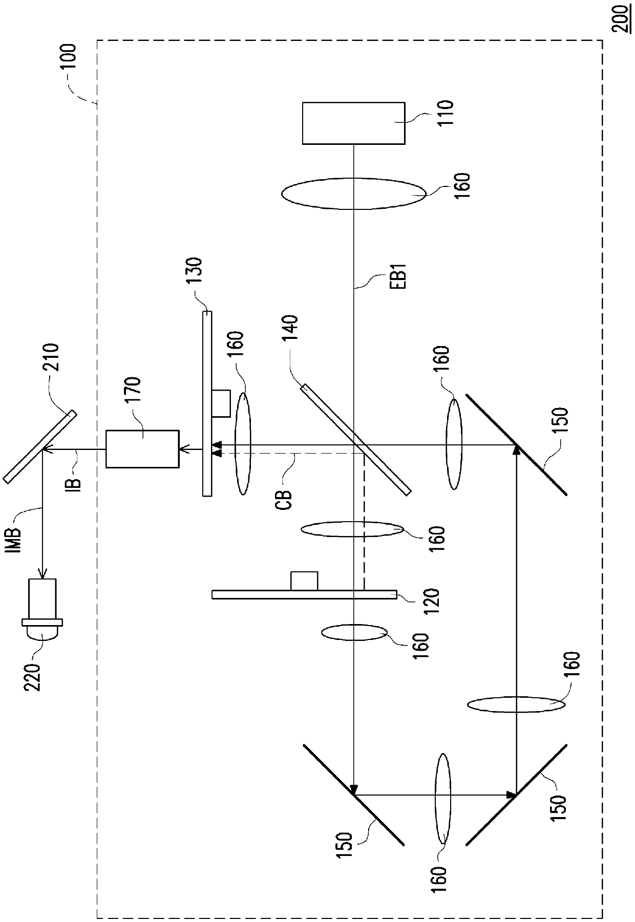
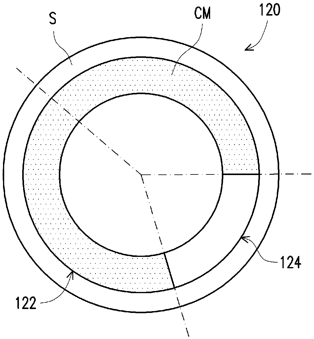
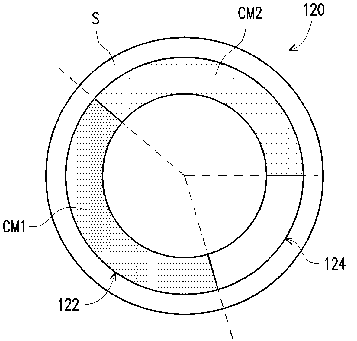
[0033] figure 1 is a schematic diagram of a projection device according to the first embodiment of the present invention. Figure 2A yes figure 1 Schematic front view of the wavelength conversion wheel in . image 3 yes figure 1 A schematic front view of an implementation of the filter wheel in . Figure 4 for image 3 The transmittance spectrum of the red filter region in . For clarity, Figure 2A , image 3 Dotted lines are deliberately drawn in subsequent related drawings to fa...


PUM

PropertyMeasurementUnit
wavelengthaaaaaaaaaa

Abstract

A lighting system comprises a first excitation light source, a wavelength conversion wheel and a filter wheel, wherein the first excitation light source is used for emitting a first excitation light beam; the wavelength conversion wheel comprises a wavelength conversion area and a first optical area; the wavelength conversion area and the first optical area cut into the transmission path of the first excitation light beam in turn; when the wavelength conversion area cuts into the transmission path of the first excitation light beam, the first excitation light beam is converted into a conversion light beam by the wavelength conversion area, and when the first optical area cuts into the transmission path of the first excitation light beam, the first excitation light beam is outputted from the first optical area; the filter wheel is arranged on a transmission path of the converted light beam and the first excitation light beam from the wavelength conversion wheel; the filter wheel comprises a first area, a second area and a blocking area; and the angle covered by the second area in the circumferential direction is smaller than the angle covered by the first optical area. A projectiondevice is also provided. The projection device using the lighting system avoids color differences in a simple manner.

Description

technical field [0001] The present invention relates to an optical system and an optical device, and in particular to an illumination system and a projection device using the illumination system. Background technique [0002] The imaging principle of the projection device is to convert the illumination light beam generated by the lighting system into an image light beam through the light valve, and then project the image light beam on the screen through the projection lens to form an image picture. The illumination system of the projection device includes a wavelength conversion wheel (wavelength conversion wheel) and a filter wheel (filter wheel), wherein the multiple optical zones of the wavelength conversion wheel correspond to the multiple filter zones of the filter wheel, so as to generate the The required color light is passed to the light valve. [0003] Generally speaking, in order to avoid color differences at the junctions between different regions, the light valv...

Claims


Application Information

Patent Timeline
Patent Type & Authority Applications(China)
IPC IPC(8): G03B21/20G02B26/00
CPCG03B21/204G02B26/008F21V9/40G03B33/08G03B21/2033G03B21/2066G02B26/00G03B21/20
Inventor 陈顺泰林淑瑜翁铭璁洪振益范辰玮
Owner CORETRONIC
Learn More