Scanning system, method and three-dimensional object manufacturing equipment for manufacturing three-dimensional objects

A technology of three-dimensional objects and scanning systems, which is applied in the direction of additive manufacturing, manufacturing tools, metal processing equipment, etc., can solve the problems of sintered workpiece strength differences, curves that cannot be guaranteed to be completely consistent, and affect the sintering quality of the workpiece, so as to improve the sintering quality and avoid Effects of Energy Differentiation and Avoidance of Color Differences

Active Publication Date: 2018-02-13
HUNAN FARSOON HIGH TECH CO LTD
View PDF7 Cites 1 Cited by
  • Summary
  • Abstract
  • Description
  • Claims
  • Application Information

AI Technical Summary

Problems solved by technology

[0003] In the specific application of the above-mentioned additive manufacturing technology, in order to expand the scanning area and improve the scanning efficiency, multiple lasers are used to scan the working area in the prior art, but the same area of ​​each layer of a work package is generally used. One laser is used for scanning sintering. However, since there are generally certain differences among the lasers, the long-term attenuation curves cannot be guaranteed to be completely consistent, resulting in differences in the strength of sintered workpieces in different regions, and because the work package of a workpiece is less Hundreds of layers, up to tens of thousands of layers, so as the number of sintering layers increases, the error is also accumulating, which seriously affects the sintering quality of the workpiece

Method used


Image

  • Scanning system, method and three-dimensional object manufacturing equipment for manufacturing three-dimensional objects
  • Scanning system, method and three-dimensional object manufacturing equipment for manufacturing three-dimensional objects

Examples


Embodiment approach

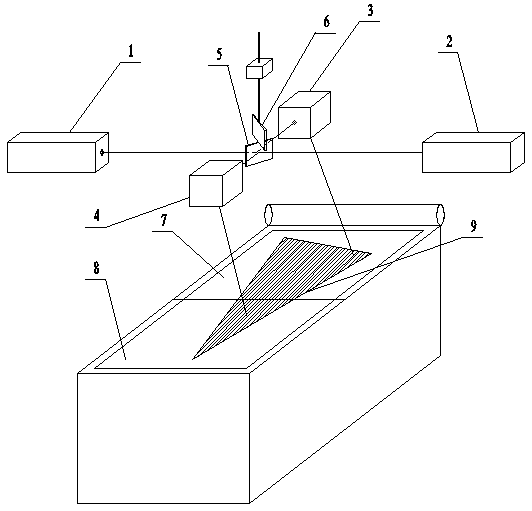
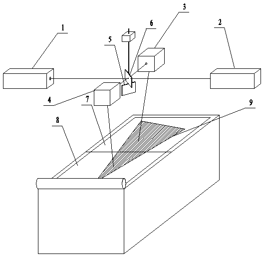
[0032] As an embodiment of the present invention, the optical path adjustment unit includes a first oscillating mirror 3, a second oscillating mirror 4, a driving unit, and two mirrors installed up and down with an angle greater than 0 degrees and less than 180 degrees. The optical lens is driven up or down by the drive unit to reflect the laser light emitted by the first laser 1 on the upper reflector 6 or lower reflector 5 of the optical lens, and the first oscillating mirror 3 or the second oscillating mirror 4 Under the control of scanning the first area 7 or the second area 8 of the sintering work area; at the same time, the reflection of the laser light emitted by the second laser 2 on the upper mirror 6 or lower mirror 5 of the optical lens, and the first vibrating mirror 3 Or under the control of the second vibrating mirror 4, the second area 8 or the first area 7 of the sintering working area is scanned.

[0033] Such as figure 1 As shown, the upper reflector 6 and t...


PUM


Abstract

A scanning system, method, and three-dimensional object manufacturing equipment for manufacturing a three-dimensional object, the scanning system includes a first laser, a second laser, an optical path adjustment unit, and a control unit, and the control unit includes: a first scanning control module for receiving When the scan instruction is reached, the laser light emitted by the first laser is scanned and sintered in the first area under the adjustment of the optical path adjustment unit, and at the same time, the laser light emitted by the second laser is scanned and sintered in the second area under the adjustment of the optical path adjustment unit; and The second scanning control module is used to scan and sinter the second area with the laser light emitted by the first laser under the adjustment of the optical path adjustment unit after the preset number of layers is scanned and sintered, and at the same time, the second area is scanned and sintered. The laser light emitted by the second laser scans and sinters the first area under the adjustment of the optical path adjustment unit. The invention enables a certain corresponding area to scan and sinter by switching different lasers, thereby improving the sintering quality of three-dimensional object parts.

Description

technical field [0001] The invention belongs to the technical field of additive manufacturing scanning, and in particular relates to a scanning system and method for manufacturing three-dimensional objects and three-dimensional object manufacturing equipment. Background technique [0002] Additive Manufacturing (AM for short) is an advanced manufacturing technology with distinctive features such as digital manufacturing, high flexibility and adaptability, direct CAD model drive, fast speed, and rich and diverse material types. Since the 1980s Since its development, it has become a pillar technology in modern advanced manufacturing technology. Selective Laser Melting (SLM) is one of the additive manufacturing technologies that has developed rapidly in recent years. It uses powder materials as raw materials and uses lasers to scan the cross-section of a three-dimensional entity layer by layer to complete prototype manufacturing. The complexity of the shape is limited, no tool...

Claims


Application Information

Patent Timeline
Patent Type & Authority Patents(China)
IPC IPC(8): B22F3/105B29C64/268B33Y30/00B33Y10/00
CPCB33Y10/00B33Y30/00B22F10/00B22F12/44B22F12/49B22F12/45B22F10/366Y02P10/25
Inventor 许小曙陈虎清周智阳曾思齐王鹏飞
Owner HUNAN FARSOON HIGH TECH CO LTD
Why Eureka
Try Eureka