
Connector

A technology of connectors and shells, which is applied in the direction of connection, parts of connection devices, electrical components, etc., can solve the problems of front bracket depression and gap, shorten the locking arm, etc., to suppress extrusion, suppress depression and gap, increase Rigid effect

Active Publication Date: 2020-03-10
YAZAKI CORP
View PDF9 Cites 2 Cited by
  • Summary
  • Abstract
  • Description
  • Claims
  • Application Information

AI Technical Summary

Problems solved by technology

[0007] However, if an attempt is made to shorten the length of the lock arm by increasing the thickness of the base in the fitting direction of the front bracket to which the root of the lock arm is connected, dents and voids may be generated when molding the front bracket due to the increased thickness

Method used


Image

  • Connector
  • Connector
  • Connector

Examples


Embodiment approach

[0085] The present invention is not limited to the above-described embodiments, and various modifications can be employed within the scope of the present invention. For example, the present invention is not limited to the above-described embodiments, and may be appropriately modified, improved, and the like. In addition, the material, shape, size, quantity, arrangement position, etc. of the constituent components in the above-described embodiments are optional and not limited as long as the purpose of the present invention can be achieved.

[0086] In the above-described embodiment, the lock arm 54 of the front bracket 5 has a two-end support beam shape in which the root portion (rear end side) is supported by the base portion 53 and the tip portion (front end side) is supported by the extension portion 55 . In contrast, the lock arm 54 may have a cantilever shape in which it supports only one of the root portion (rear end side) and the front end portion (front end side).

[...


PUM


Abstract

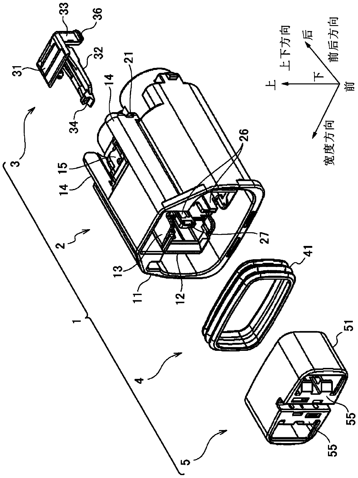
A connector includes a housing and a holder. The housing includes a terminal housing chamber housing terminals and a support portion in which a first locking portion for locking the holder in the temporary locking position is formed. The holder is mounted on the housing so as to be movable in a fitting direction of the housing and a mating housing between a temporary locking position and a main locking position. The holder is configured to be immovable from the temporary locking position to the main locking position when the terminal inserted into the terminal housing chamber is in a halfway insertion position and is configured to be movable from the temporary locking position to the main locking position when the terminal is in a normal insertion position.

Description

technical field [0001] The invention relates to a connector. Background technique [0002] In the prior art, it is well known that a connector including a housing provided with a terminal accommodating chamber for receiving a terminal is provided with a front holder for detecting a midway insertion state of a terminal inserted into the terminal accommodating chamber (see, for example, Patent Document 1). [0003] The front bracket is mounted on the housing so as to be movable between the temporary locking position and the main locking position in the fitting direction of the housing and the mating housing. The front support frame is configured to be movable from the temporary locking position to the primary locking position when the terminal is in the normal insertion position, and is non-movable from the temporary locking position to the primary locking position when the terminal is in the midway insertion position. In this way, when the terminal is at the midway insertio...

Claims


Application Information

Patent Timeline
Patent Type & Authority Applications(China)
IPC IPC(8): H01R13/436H01R13/502
CPCH01R13/4365H01R13/4368H01R13/502H01R13/506H01R13/5025
Inventor 泽入薫
Owner YAZAKI CORP
Learn More