
Cable cover

a cable cover and cable technology, applied in the field of cable covers, can solve the problems of large load applied to the electrical wire, large load applied to the coupling device connection, etc., and achieve the effects of increasing the number of portions, reducing the generation of vibration, and increasing the coupling strength of the pair of divided bodies

Active Publication Date: 2020-01-07
JST MFG CO LTD
View PDF21 Cites 0 Cited by
  • Summary
  • Abstract
  • Description
  • Claims
  • Application Information

AI Technical Summary

Benefits of technology

[0009]In light of the circumstances described above, an object of the present invention is to provide a cable cover that suppresses the pinching of a cable during assembly of the cable cover, and reduces the load that is applied to the cable inside the cable cover.
[0021]According to this configuration, the coupling strength of the pair of divided bodies can be further raised by the fitting of the protrusion portion into the recession portion. Also, due to the fitting of the protrusion portion into the recession portion, it is possible to further increase the number of portions of the pair of divided bodies that are in contact with each other. Accordingly, it is possible to more reliably suppress the generation of vibration between the pair of divided bodies. This therefore makes it possible to realize a cable cover that is particularly suitable for locations where vibration is generated.

Problems solved by technology

However, the electrical wire protection rib disclosed in the specification of JP 5664921B is shaped so as to protrude toward a bent portion of the electrical wire, and a large load tends to be applied to the electrical wire when it comes into contact with the electrical wire.
In particular, in the case where tensile force acts on the electrical wire for example, if the electrical wire is forcibly brought into contact with the electrical wire protection rib, a large load is applied to the electrical wire.

Method used


Image

  • Cable cover
  • Cable cover
  • Cable cover

Examples


Embodiment Construction

[0035]Hereinafter, modes for carrying out the present invention will be described with reference to the drawings. Note that the present invention is broadly applicable to various applications as a cable cover that covers at least a portion of a cable that extends out from an electrical connector.

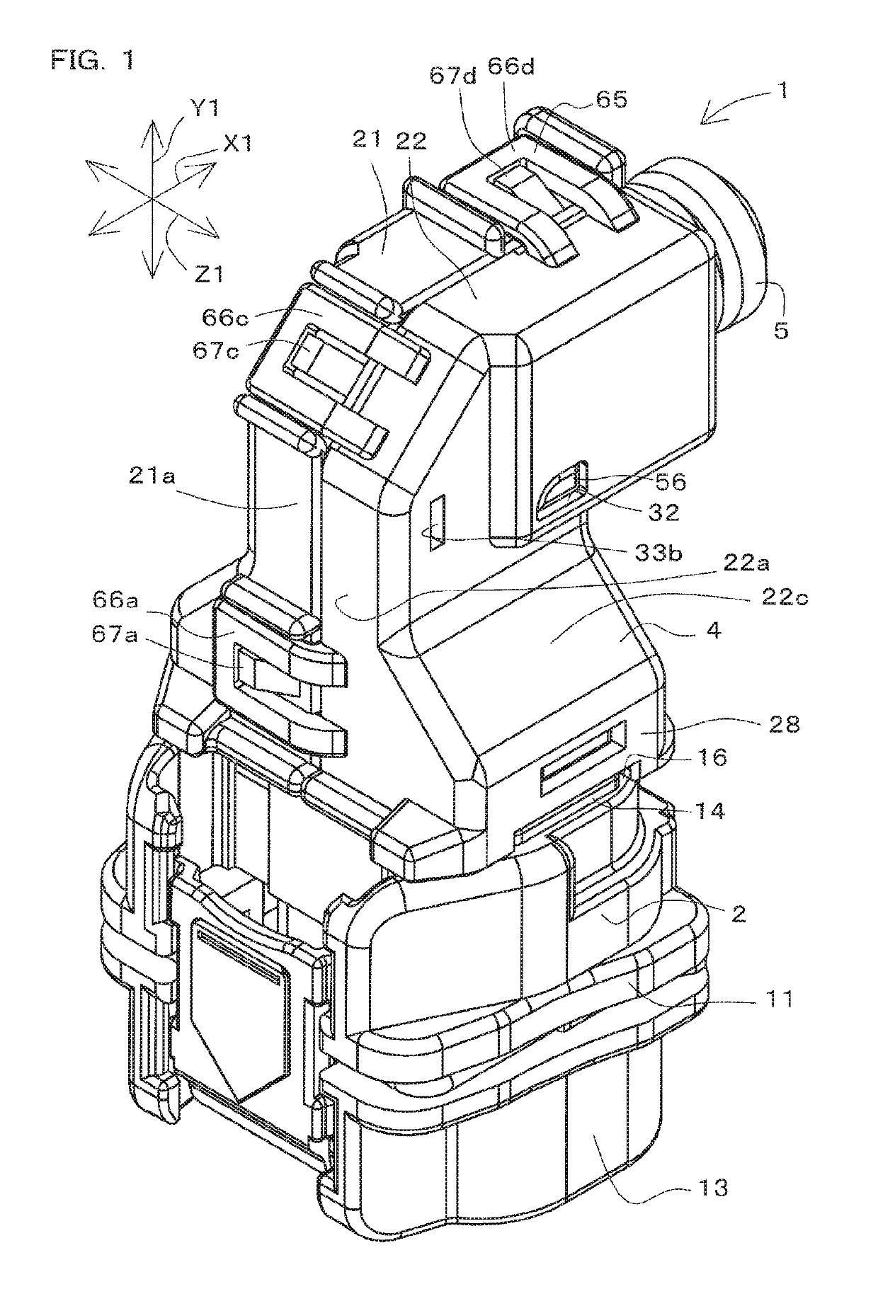
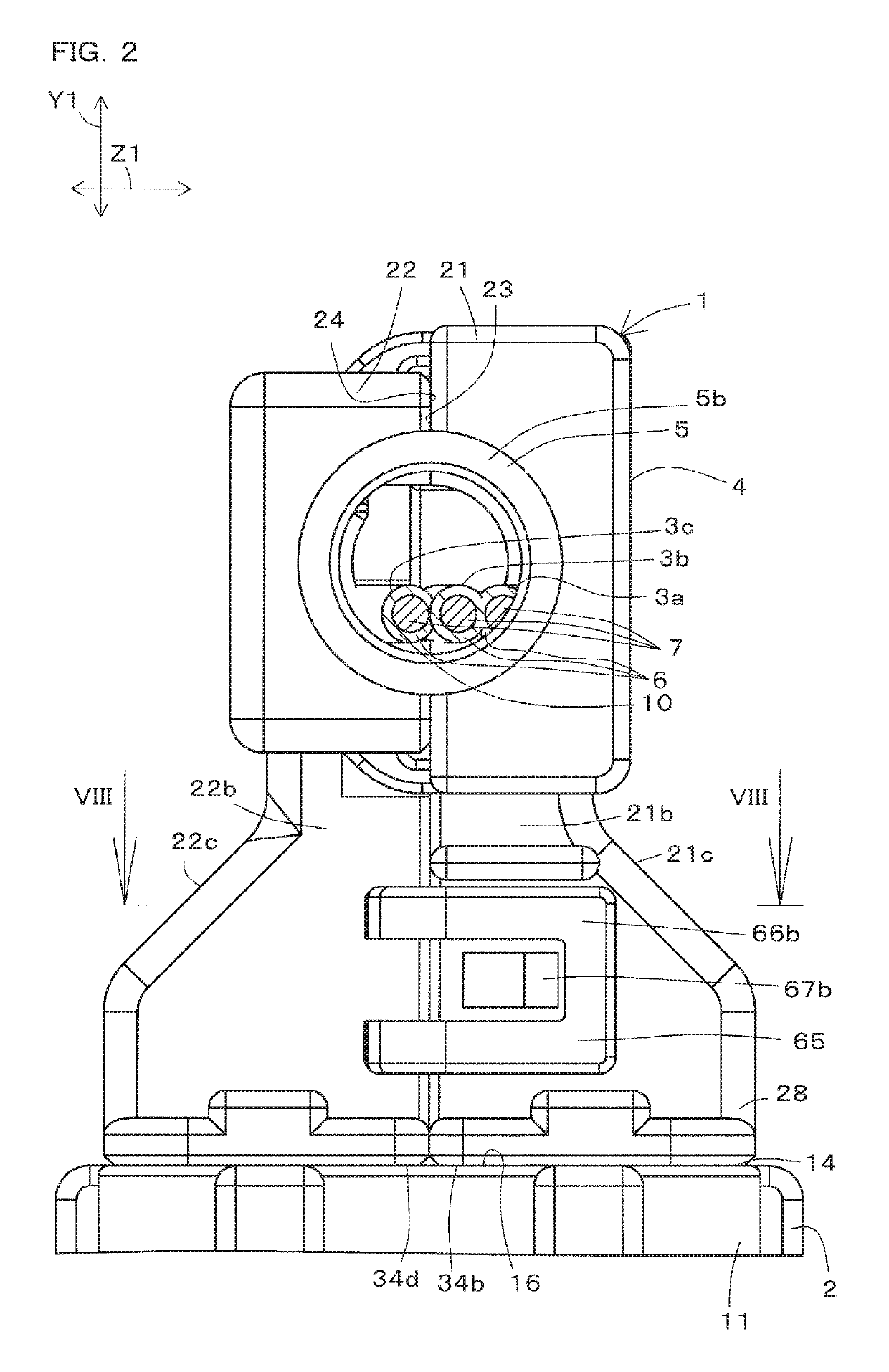
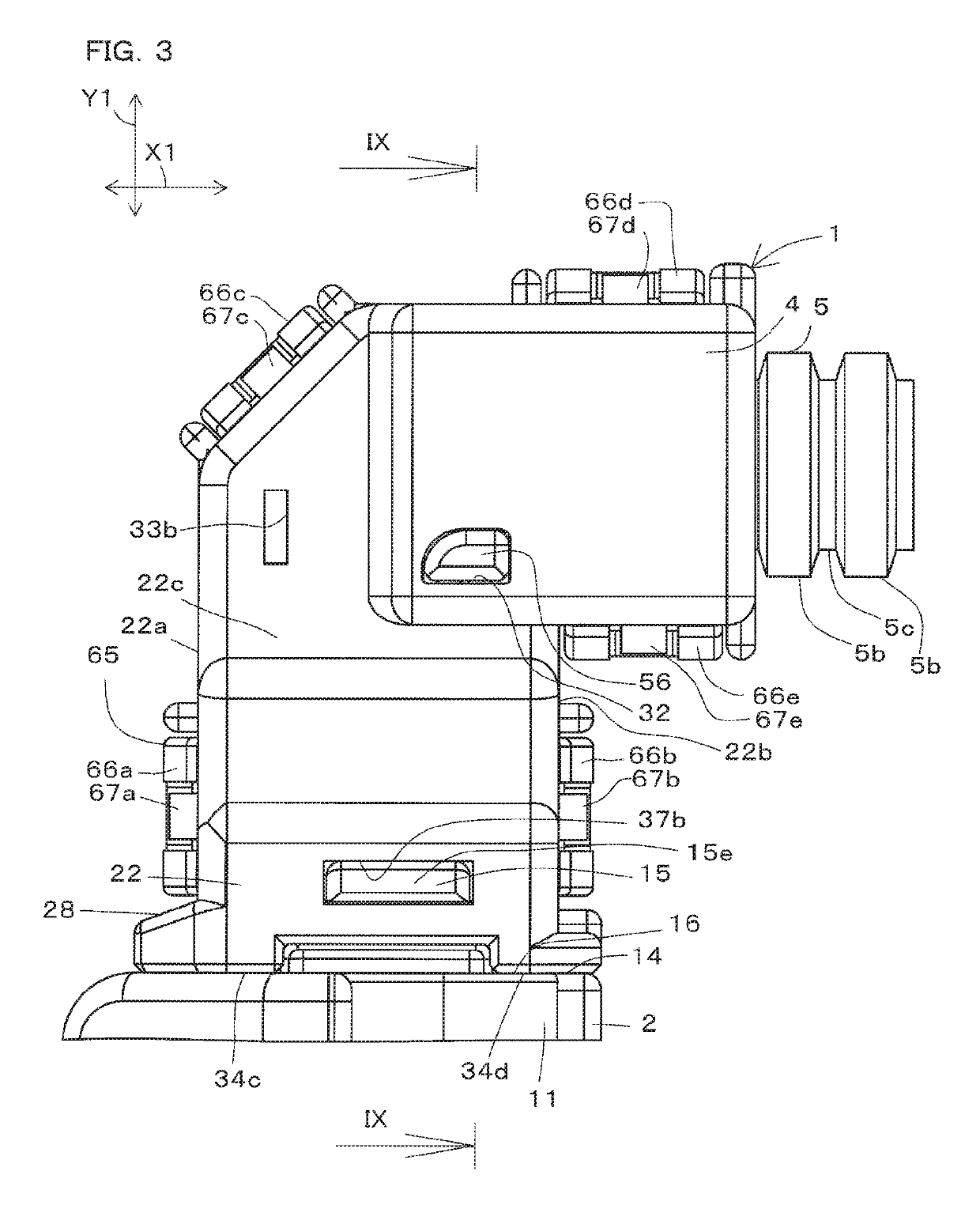
[0036]FIG. 1 is a perspective view of a connector unit 1 according to an embodiment of the present invention, in which cables 3a, 3b, and 3c are not shown. FIG. 2 is a front view of a portion of the connector unit 1. FIG. 3 is a side view of a portion of the connector unit 1. FIG. 4 is a bottom view of the connector unit 1. FIG. 5 is a perspective view of the connector unit 1, in which portions of the cables 3a, 3b, and 3c and a second divided body 22 of a cable cover 4 are not shown.

[0037]FIG. 6 is a side view of the connector unit 1, in which portions of the cables 3a, 3b, and 3c and the second divided body 22 of the cable cover 4 are not shown. FIG. 7 is a rear view of the connector unit ...


PUM


Abstract

A cable cover of this invention is used for guiding the orientation of a cable that extends out from a connector. This cable cover includes a pair of divided bodies, a cable passage, and a supporting portion. The pair of divided bodies have a pair of joining faces that are to be joined to each other. The cable passage includes a bent passage portion for housing a bent portion of the cable. The supporting portion extends as a curved surface along the forward direction of the cable in the bent passage portion, and is configured to be able to support an inward portion of the bend in the bent portion.

Description

CROSS-REFERENCE TO RELATED APPLICATION[0001]This application claims priority to Japanese Patent Application No. 2015-248777. The entire disclosure of Japanese Patent Application No. 2015-248777 is hereby incorporated herein by reference.BACKGROUND OF THE INVENTION[0002]1. Field of the Invention[0003]The present invention relates to a cable cover for provision on a cable that extends out from an electrical connector.[0004]2. Description of Related Art[0005]A connector cover for attachment to an electrical connector is known (e.g., see the specification of JP 5664921B). The connector cover is used for making a 90° change, for example, in the orientation of an electrical wire that extends out from the housing of the electrical connector. The cover disclosed in the specification of JP 5664921B is attached to the housing of the electrical connector.[0006]The cover has a pair of divided bodies. These two divided bodies are joined to each other so as to sandwich one end portion of the hous...

Claims


Application Information

Patent Timeline
Patent Type & Authority Patents(United States)
IPC IPC(8): H02G3/04F16L3/10H02G15/007H01R13/56H02G3/06
CPCH01R13/562H02G15/007H02G3/0691H02G3/0462F16L3/1091H01R13/502
Inventor TERASHIMA, TOSHIHIROFUJII, TOMOYA
Owner JST MFG CO LTD
Learn More