a pressure control valve

A pressure control and pressure technology, which is applied in fluid pressure actuation devices, accumulator devices, earth movers/shovels, etc., can solve problems such as bucket material spilling, boom cylinder retraction, etc.

Active Publication Date: 2021-06-01
温州英斯蒙特自动化仪表有限公司
View PDF17 Cites 0 Cited by
  • Summary
  • Abstract
  • Description
  • Claims
  • Application Information

AI Technical Summary

Problems solved by technology

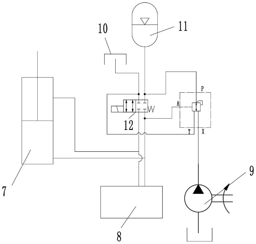
[0004] In the above two technologies, because the solenoid valve controls the accumulator to communicate with the rodless chamber of the boom cylinder for liquid filling during a certain operation process, the unequal load will cause the vibration reduction function to be realized At this time, the pressure of the boom cylinder is not equal to the pressure of the accumulator, so that the boom cylinder suddenly extends or retracts, which in turn causes the material in the bucket to scatter

Method used


Image

  • a pressure control valve
  • a pressure control valve
  • a pressure control valve

Examples


Embodiment Construction

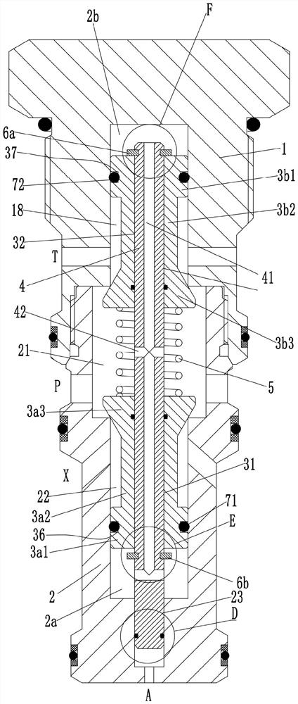
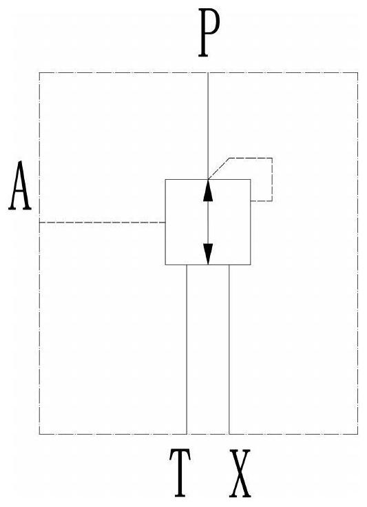
[0024] see Figure 1-6 As shown, a pressure control valve includes a valve sleeve 2, a screw sleeve 1, and a valve control assembly. The valve sleeve 2 is provided with a valve chamber 21 with an upper end opening, and the screw sleeve 1 is threadedly connected to the upper end of the valve sleeve 2. The bottom of the valve cavity 21 in the valve sleeve 2 is provided with a lower valve hole 22 axially downward, and the bottom of the valve hole 22 in the valve sleeve 2 is provided with a sliding hole 23 downward along its axial direction, so The screw sleeve 1 is provided with an upper valve hole 18 on the end face facing the valve chamber 21; the side of the valve sleeve 2 is provided with a P port communicated with the valve chamber 21, and an X port communicated with the lower valve hole 22. The lower end of the valve sleeve 2 is provided with an A port communicating with the sliding hole 23, and the side of the screw sleeve 1 is provided with a T port communicating with the...


PUM


Abstract

The invention discloses a pressure control valve, which comprises a valve sleeve, a screw sleeve, and a valve control assembly. The valve sleeve is provided with a valve cavity with an upper end open, and the screw sleeve is threadedly connected to the upper end of the valve sleeve; the valve sleeve The bottom of the inner valve cavity is provided with a lower valve hole along its axial direction, the bottom of the lower valve hole is provided with a sliding hole in the valve sleeve, and the upper valve hole is provided on the end face of the screw sleeve facing the valve cavity; The side of the valve sleeve is provided with a P port and an X port, the lower end of the valve sleeve is provided with an A port, and the side of the screw sleeve is provided with a T port communicating with the upper valve hole; the lower valve hole is slidingly connected with a second A plug body, the upper end of the first plug body is provided with a first connecting column, and the upper end of the first connecting column is provided with a first cone valve body; a second plug body is slidably connected in the upper valve hole, and the second plug body The lower end is provided with a second connecting column, and the lower end of the second connecting column is provided with a second cone valve body; the pressure control valve is not only simple in structure, compact in volume, but also can effectively realize that the pressure of the accumulator is equal to the pressure of the rodless chamber of the boom cylinder.

Description

technical field [0001] The invention belongs to the technical field of hydraulic valves, in particular to a pressure control valve. Background technique [0002] The wheel side supports of construction machinery such as loaders, skid steer loaders, backhoe loaders and telescopic forklifts are rigidly connected to the frame, and the excitation vibration caused by uneven road surfaces is completely borne by the four tires. When the above-mentioned construction machinery is in the process of driving or working, the boom cylinder does not move, and the boom, boom cylinder, and front frame are similar to rigid connections at this time. Due to the effect of road conditions and tires, the whole vehicle will center on the front axle. Swinging will sometimes cause the rear axle to break away from the ground, and the driver's body will swing with the vehicle at this time, making it difficult to control and driving comfort is very poor. Because the working device, heavy objects and ot...

Claims


Application Information

Patent Timeline
Patent Type & Authority Patents(China)
IPC IPC(8): F15B13/02F15B1/02E02F9/22E02F9/20
CPCE02F9/2079E02F9/2267F15B1/021F15B13/02
Inventor 陈艳艳
Owner 温州英斯蒙特自动化仪表有限公司
Why Eureka
Try Eureka