
Terminal inserting and capping mechanism of optical fiber connector

A technology of optical fiber connector and terminal insertion device, which is applied in the field of optical fiber, and can solve the problems that the terminal cannot be straightened, easily tilted, and difficult to insert the terminal.

Inactive Publication Date: 2020-03-13
DONGGUAN RONGGONG AUTOMATION TECH CO LTD
View PDF0 Cites 2 Cited by
  • Summary
  • Abstract
  • Description
  • Claims
  • Application Information

AI Technical Summary

Problems solved by technology

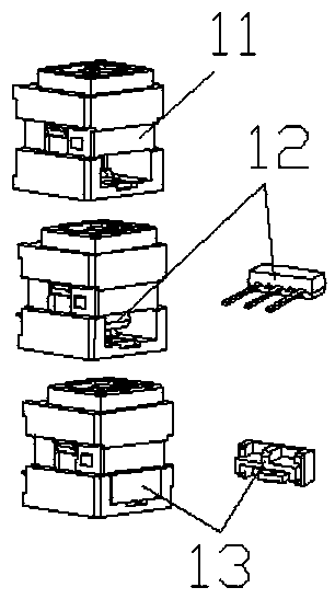
[0002] With the rapid development of the Internet, the application of optical fiber is becoming more and more extensive. The indispensable components in the optical fiber are optical fiber connectors, such as figure 2 As shown, the optical fiber connector includes a main body 11, and a socket is opened on the main body. It is necessary to insert the terminal 12 from the socket into the main body 11, and make the tip of the terminal pass through the main body 11, and then install the cover 13 to clamp the terminal tightly. The specific structure of the terminal is composed of a block and pins. When inserting, the terminal cannot be straightened and is easy to tilt, which makes it very difficult to insert the terminal by pushing the component. In view of this situation, the existing structure Most of them are assembled manually, and the assembly efficiency is low

Method used


Image

  • Terminal inserting and capping mechanism of optical fiber connector
  • Terminal inserting and capping mechanism of optical fiber connector
  • Terminal inserting and capping mechanism of optical fiber connector

Examples


Embodiment Construction

[0022] In order to enable those skilled in the art to better understand the technical solution of the present invention, the present invention will be described in detail below in conjunction with the accompanying drawings. The description in this part is only exemplary and explanatory, and should not have any limiting effect on the protection scope of the present invention. .

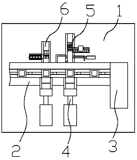
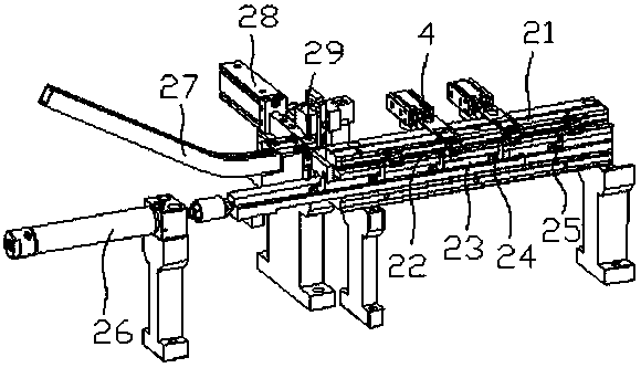
[0023] Such as Figure 1-2 , 7-8, the specific structure of the present invention is: a terminal insertion capping mechanism for an optical fiber connector, including a frame 1, the frame 1 is provided with a delivery device 3 that cooperates with the main body 11, and the The starting end of the conveying device 3 is equipped with a main body feeding device 3, and the rear side of the conveying device 3 is sequentially opened with two fitting ports for terminal and cover assembly along the conveying direction, and is equipped with a terminal insertion device respectively 5 and a cover insertion devic...


PUM


Abstract

The invention relates to a terminal inserting and capping mechanism of an optical fiber connector. The mechanism comprises a rack. A conveying device is arranged on the rack. A main feeding device isarranged at the starting end of the conveying device in a matching manner. Two matching openings are formed in the rear side of the conveying device, and are respectively matched with a terminal inserting device and a sealing cover inserting device. The terminal inserting device comprises a terminal inserting groove which is in butt joint with the corresponding matching opening and is arranged inthe front-back direction. The side surface of the terminal inserting groove is matched with a terminal conveying groove, and the terminal conveying groove is a groove body which is matched with a terminal structure and enables a terminal to be conveyed horizontally. A terminal inserting cylinder is arranged at the rear end of the terminal inserting groove. The terminal inserting cylinder is connected with a terminal inserting pushing assembly. The terminal inserting pushing assembly comprises a terminal inserting movable block. The terminal inserting movable block is connected with a terminalinserting pushing rod with the same height as a terminal block body. The terminal inserting movable block is further connected with a terminal inserting pressing block through a terminal inserting spring, and the lower surface of the terminal inserting pressing block is tangent to the terminal inserting pushing rod. Automatic inserting of the terminal can be realized.

Description

technical field [0001] The invention relates to the field of optical fibers, in particular to a terminal insertion sealing mechanism of an optical fiber joint. Background technique [0002] With the rapid development of the Internet, the application of optical fiber is becoming more and more extensive. The indispensable components in the optical fiber are optical fiber connectors, such as figure 2 As shown, the optical fiber connector includes a main body 11, and a socket is opened on the main body. It is necessary to insert the terminal 12 from the socket into the main body 11, and make the tip of the terminal pass through the main body 11, and then install the cover 13 to clamp the terminal tightly. The specific structure of the terminal is composed of a block and pins. When inserting, the terminal cannot be straightened and is easy to tilt, which makes it very difficult to insert the terminal by pushing the component. In view of this situation, the existing structure Mos...

Claims


Application Information

Patent Timeline
IPC IPC(8): G02B6/38
CPCG02B6/3869G02B6/3898
Inventor 邓宇军肖杰康
Owner DONGGUAN RONGGONG AUTOMATION TECH CO LTD
Learn More