Microscope for automatic microscopic examination
A microscope and microscope inspection technology, applied in the field of microscopy, can solve the problems that the microscope occupies a large space, the structure of the microscope is complex, and the overall structure is too large
- Summary
- Abstract
- Description
- Claims
- Application Information
AI Technical Summary
Problems solved by technology
Method used
Image
Examples
Embodiment 1
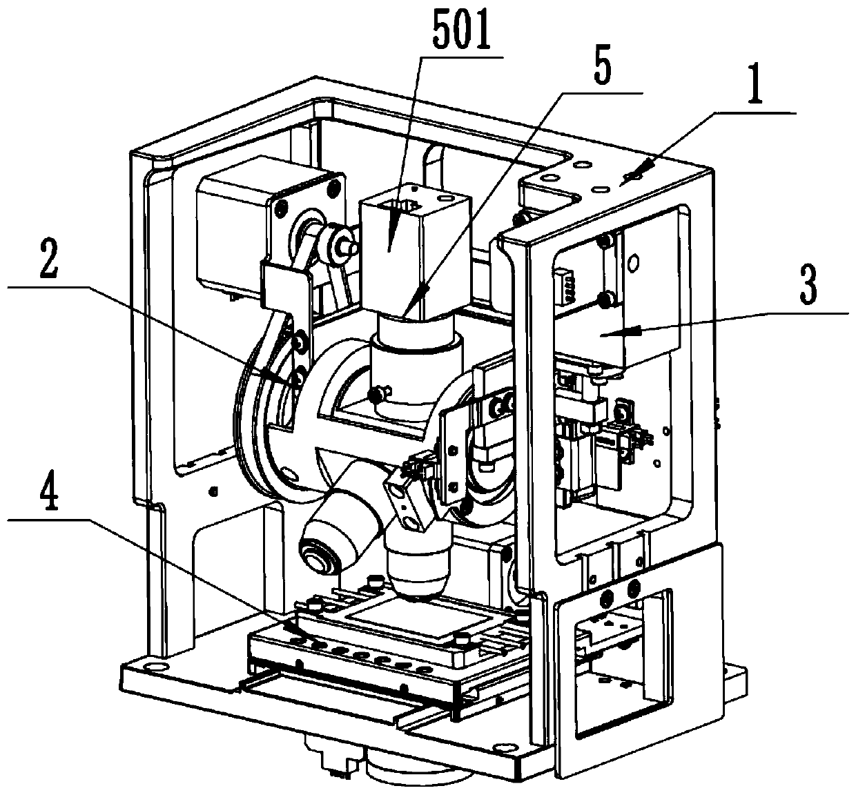
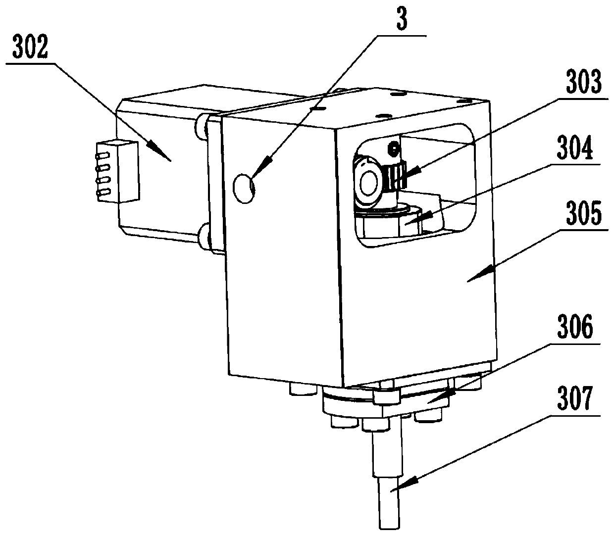
[0033] Such as Figure 1-7 As shown, a microscope for automatic mirror inspection includes a frame 1, an objective lens switching assembly 2 slidably connected to the frame 1, a focusing assembly 3 for driving the objective lens switching assembly 2 up and down, a stage assembly 4, The camera assembly 5, the focusing assembly 3 is arranged on the frame 1, the stage assembly 4 is arranged on the frame 1, the camera assembly 5 is arranged on the objective lens switching assembly 2, and the object stage assembly 4 is located on the objective lens Toggle component 2 below.
[0034] The working process of this embodiment is: put the sample on the stage assembly 4, wait for the sample to settle and then start taking pictures. According to the coordinate parameters set by the application software, the stage assembly 4 will automatically translate, and the required The captured sample moves to directly below the objective lens. Then the focusing assembly 3 drives the objective lens ...
Embodiment 2
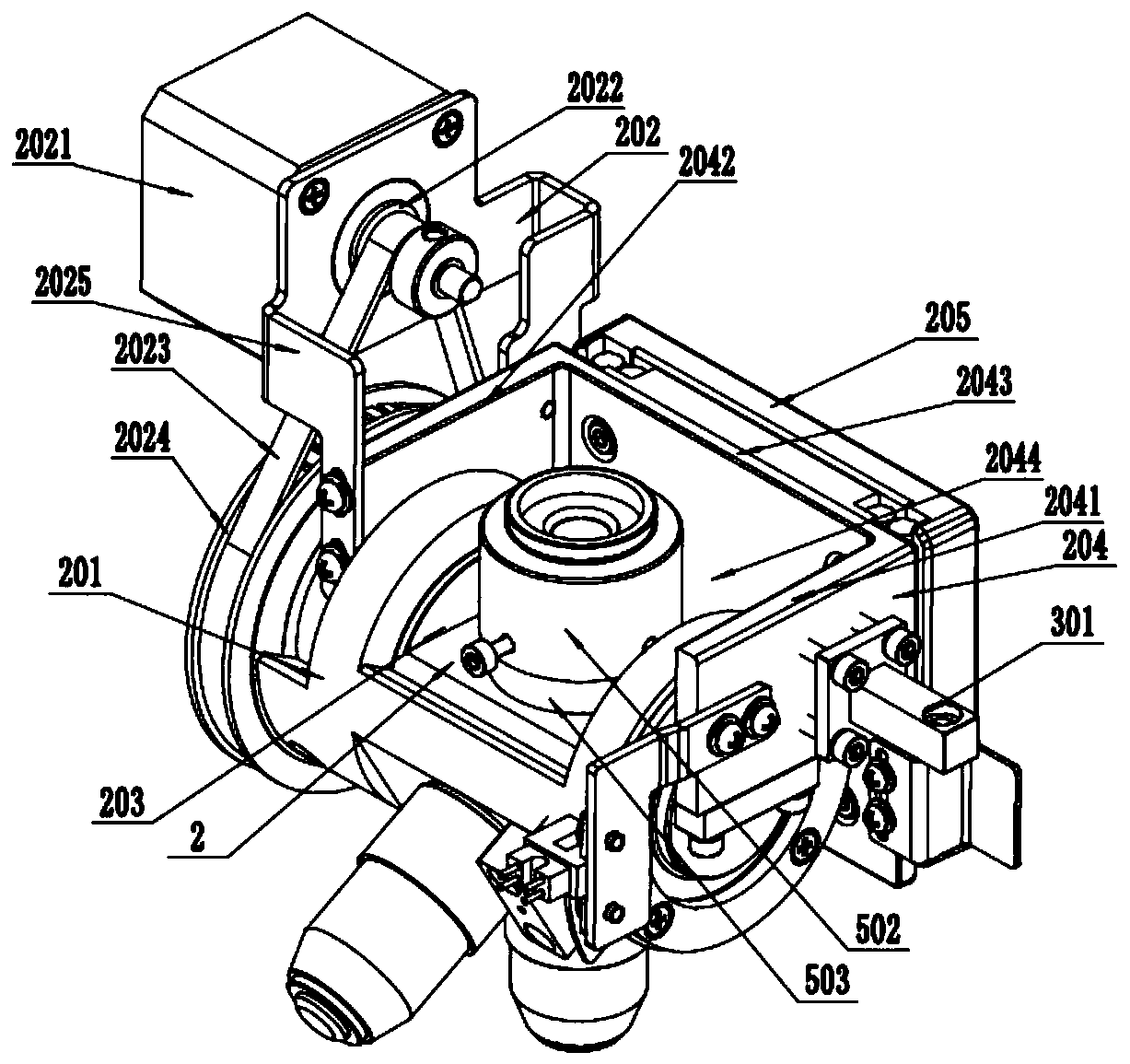
[0036] Such as Figure 1-7 As shown, this embodiment is further limited on the basis of Embodiment 1. The objective lens switching assembly 2 includes a rotating shaft 201 for installing an objective lens, a power unit 202 for driving the rotating shaft 201 to rotate, a fixed shaft 203, a second A lifting plate 204, a second lifting plate 205 installed on the frame, the first lifting plate 204 is slidingly connected with the second lifting plate 205, the first lifting plate 204 is connected with the focusing assembly 3, and the fixed shaft 203 Set on the first lifting plate 204 , the rotating shaft 201 is sleeved on the fixed shaft 203 , and the rotating shaft 201 can rotate around the fixed shaft 203 .
[0037] Further, the first lifting plate 204 is a U-shaped structure, and the U-shaped structure includes a first connecting end 2041, a second connecting end 2042, and a lifting end 2043. The two sides parallel to each other in the U-shaped structure are respectively the firs...
Embodiment 3
[0042] Such as Figure 1-7 As shown, this embodiment is further limited on the basis of Embodiment 1, the stage assembly 4 includes a base 401 for mounting on the frame 1, and a first slider 402 slidingly connected to the base 401 , the second slider 403 slidingly connected with the first slider 402, the first driving device 404 for driving the first slider, the second driving device 405 for driving the second slider 403, the The light source assembly 406 , the first slider 402 is arranged on the top surface of the base 401 , the second slider 403 is arranged on the top surface of the first slider 402 , and the light source assembly 406 is arranged on the bottom surface of the base 401 .
[0043] Further, the base 401 and the first sliding block 402, and the first sliding block 402 and the second sliding block 403 are all slidably connected through cross guide rails.
[0044] Further, the first driving device 404 includes a first lead screw motor 4041, a first bracket 4042, a...
PUM
 Abstract
Description
Claims
Application Information
 - R&D
- Intellectual Property
- Life Sciences
- Materials
- Tech Scout
- Unparalleled Data Quality
- Higher Quality Content
- 60% Fewer Hallucinations
Browse by: Latest US Patents, China's latest patents, Technical Efficacy Thesaurus, Application Domain, Technology Topic, Popular Technical Reports.
© 2025 PatSnap. All rights reserved.Legal|Privacy policy|Modern Slavery Act Transparency Statement|Sitemap|About US| Contact US: help@patsnap.com


