Visual sensor working state test method

A visual sensor and working state technology, applied in the field of sensor testing, can solve problems such as easy misjudgment, closed-loop testing, and high risk of leaving the factory, and achieve the effects of eliminating judgment errors, improving testing efficiency, and reducing dependence

Pending Publication Date: 2020-03-13
易思维(杭州)科技有限公司
View PDF0 Cites 7 Cited by
  • Summary
  • Abstract
  • Description
  • Claims
  • Application Information

AI Technical Summary

Problems solved by technology

[0014] A. Testers cannot observe the entire process of command execution, cannot ensure that the sensor operates correctly during the test, and the test does not reach a closed loop;
[0015] B. Changes in lasers, light sources and other components cannot be accurately judged during the test, which is prone to misjudgments and test results are unreliable;
[0016] C. It is impossible to fully test the equipment performance and device stability, and the risk of leaving the factory is high;
[0017] D. During the accuracy test, it is easily affected by the external environment, such as relative position deviation caused by collision and vibration, the working distance does not reach the specified value, and the ambient light interference is too strong and other factors affect the accuracy of the test results;

Method used


Image

  • Visual sensor working state test method
  • Visual sensor working state test method
  • Visual sensor working state test method

Examples


Embodiment Construction

[0051] The technical solutions of the present invention will be described in detail below in conjunction with the accompanying drawings and embodiments.

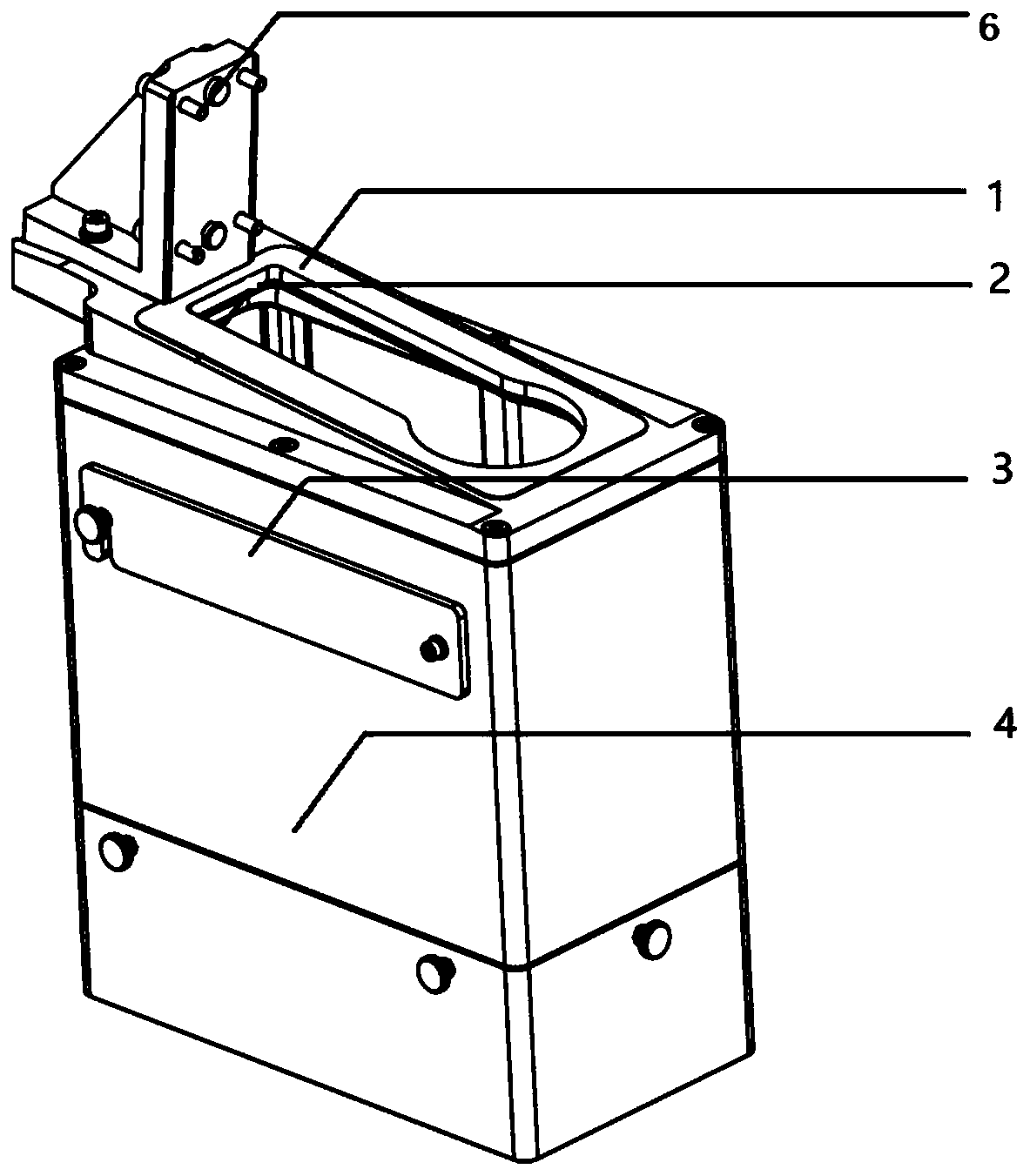
[0052] A kind of visual sensor working condition testing method, the measuring part of visual sensor comprises: camera and part 1, comprises the following steps:

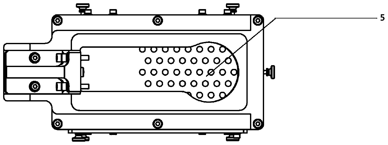
[0053] 1) Fix the vision sensor to be tested on the test device, such as figure 1 As shown, the visual sensor can be fixed on the positioning bracket 6 by screws, covering the opening 1 of the test device, and the inner cavity 2 of the test device forms a closed dark room; in the test device, a target 5 ( Such as figure 2 shown);

[0054] The visual sensor to be tested is fixed on the test device, and when the working state is manually determined to be normal, the image of the target under the open or closed state of the acquisition part 1 is respectively collected, stored, and used as a standard image under different states; then according to step 2) Carry out...


PUM


Abstract

The invention discloses a visual sensor working state test method, which comprises the following steps that a visual sensor to be tested is fixed on a test device, and a closed darkroom is formed in an inner cavity of the test device; a target is arranged in a camera view field range of the visual sensor; according to the preset test flow, the camera is used for acquiring an image of the target when the component I is in an open/closed state; and the gray comparison analysis or template matching is carried out on the acquired image and a standard image acquired in a corresponding state of eachmoment of a preset test flow; according to the test method, the dependence of the test process on personnel is reduced, the judgment error caused by subjective judgment is eliminated, and the reliability of the test result is improved.

Description

technical field [0001] The invention relates to the field of sensor testing, in particular to a method for testing the working state of a visual sensor. Background technique [0002] The visual sensor uses the camera to obtain the image information of the measured object, and then analyzes the characteristics of the measured object according to the image information, such as defect detection, positioning recognition, etc. In order to meet the needs of different measurement scenarios, the visual sensor is often equipped with a light source and / or other measurement components (such as lasers, projectors), when the production and assembly of the visual sensor is completed, it is necessary to check whether the functions contained in its design specifications are complete; whether the stability of the coordination state of the measurement parts, light source and camera is qualified, the traditional test methods and shortcomings are as follows : [0003] 1. Manual testing: [00...

Claims


Application Information

Patent Timeline
Patent Type & Authority Applications(China)
IPC IPC(8): G06T7/00G06K9/62G06K9/46G01D18/00
Inventor 杨欣蕊陈仙勇郭孟宇吕猛
Owner 易思维(杭州)科技有限公司
Why Eureka
Try Eureka