Heat dissipation unit and heat dissipation device thereof

A heat dissipation unit and heat dissipation device technology, which is applied in the direction of electrical components, cooling/ventilation/heating transformation, instruments, etc., can solve the problems of large volume and poor heat dissipation efficiency of heat dissipation devices, and achieve the effect of small size and extremely poor heat dissipation efficiency

Pending Publication Date: 2020-03-13
ASIA VITAL COMPONENTS (CHINA) CO LTD
View PDF0 Cites 0 Cited by
  • Summary
  • Abstract
  • Description
  • Claims
  • Application Information

AI Technical Summary

Problems solved by technology

[0005] 1. Extremely poor cooling efficiency;
[0006] 2. The cooling device is too large

Method used


Image

  • Heat dissipation unit and heat dissipation device thereof
  • Heat dissipation unit and heat dissipation device thereof
  • Heat dissipation unit and heat dissipation device thereof

Examples


Embodiment Construction

[0044] The above objects of the present invention and their structural and functional characteristics will be described with reference to the preferred embodiments of the accompanying drawings.

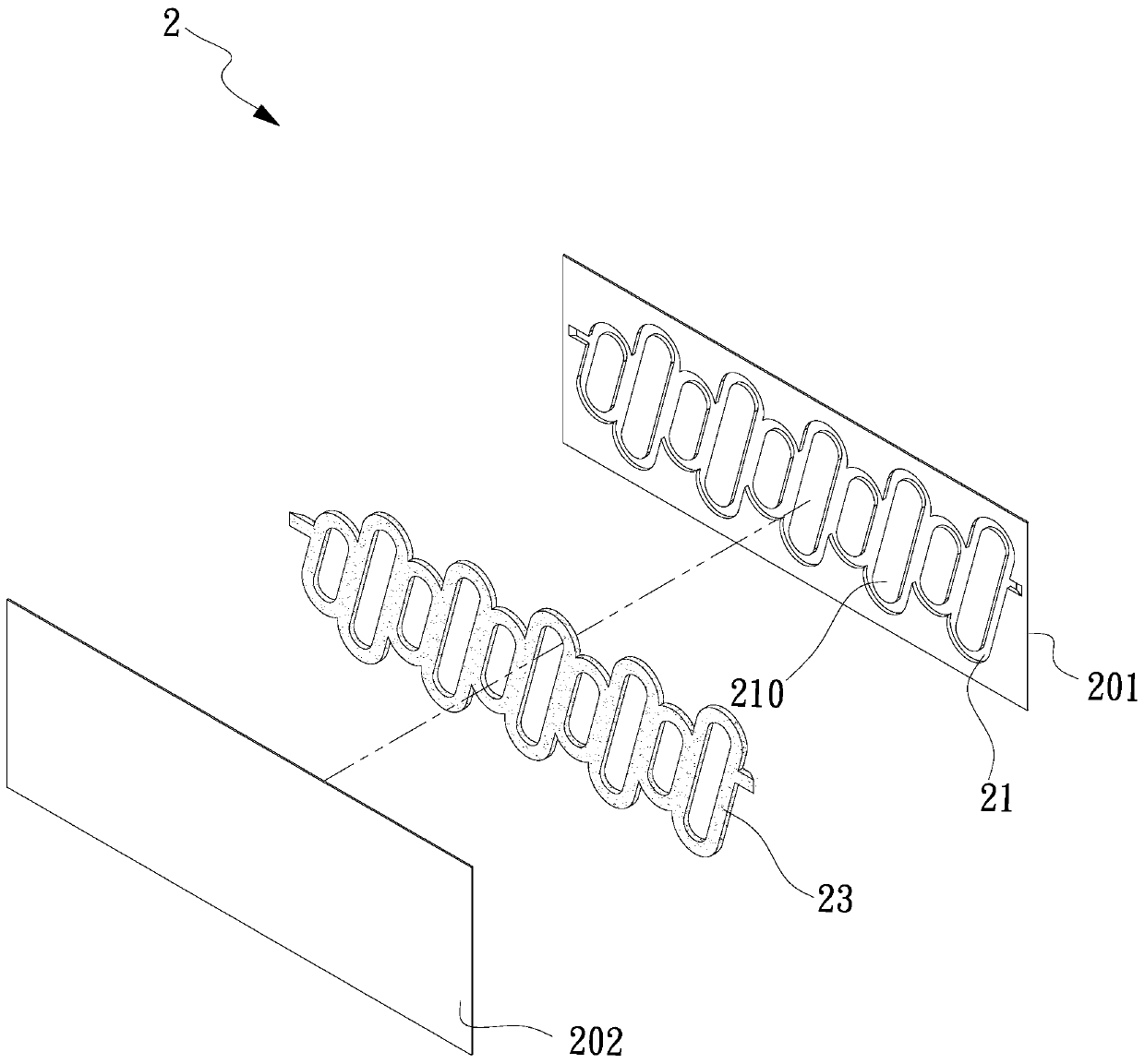
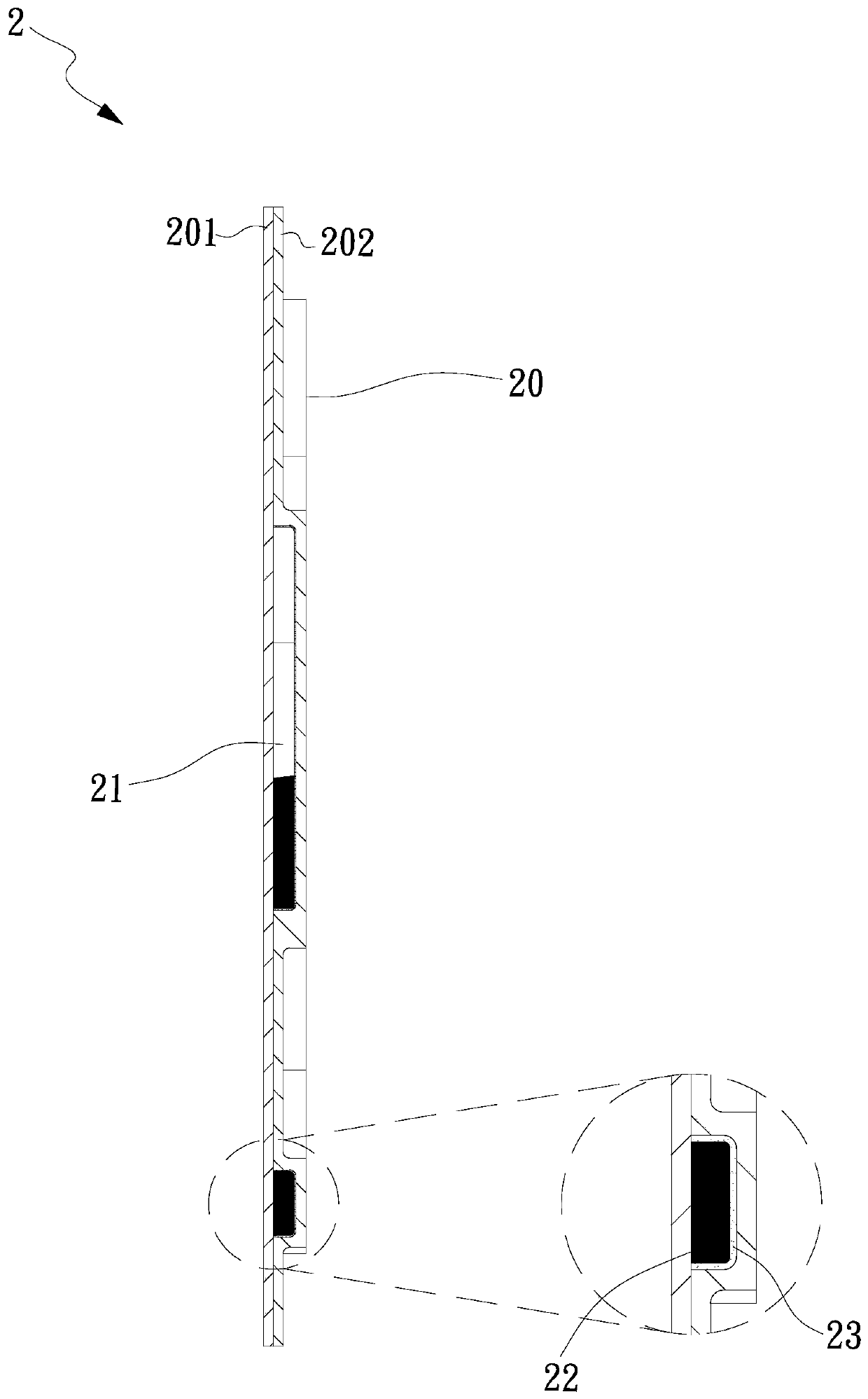
[0045] see figure 1 , figure 2 , is a perspective exploded view and a cross-sectional view of the first embodiment of the heat dissipation unit of the present invention. As shown in the figure, a heat dissipation unit 2 has at least one heat dissipation fin 20, and the heat dissipation fin 20 is formed by a first plate body 201. and a second plate body 202 correspondingly covered, in this embodiment, at least one groove 210 is formed on the first plate body 201 (of course, the second plate body 202 can be optionally formed with the above-mentioned groove 210 ). The groove 210 is described by the first plate body 201 in this embodiment). More specifically, the first plate body 201 of the heat dissipation fin 20 in this embodiment has a groove 210 structure, and the second plate body ...


PUM


Abstract

The invention provides a heat dissipation unit and a heat dissipation device thereof. The heat dissipation device comprises a base and the radiating unit, the base is provided with a first side and asecond side, and the heat dissipation unit is provided with at least one heat dissipation fin correspondingly arranged at the first side. The heat dissipation fin is formed by correspondingly coveringa first plate body and a second plate body, the first plate body and the second plate body jointly define a plurality of independent flow channels, and the independent flow channels are communicatedwith each other and are filled with the working fluid.

Description

technical field [0001] The present invention relates to a heat dissipation unit and a heat dissipation device thereof, in particular to a heat dissipation unit and a heat dissipation device thereof which greatly increase the heat dissipation efficiency. Background technique [0002] The current mobile devices, personal computers, servers, communication boxes or other systems or devices have improved computing performance, and the heat generated by their internal computing units has also increased, so relatively more heat dissipation units are needed to assist their heat dissipation. Most manufacturers use heat dissipation components such as radiators, heat pipes, and vapor chambers with fans for auxiliary heat dissipation, and when large areas are required for heat dissipation, they use heat dissipation devices (radiators) and cooling fans for forced heat dissipation. [0003] Generally, common heat dissipation devices (heat sinks) in the industry are composed of a substrate...

Claims


Application Information

Patent Timeline
Patent Type & Authority Applications(China)
IPC IPC(8): H05K7/20G06F1/20
CPCG06F1/20H05K7/20327H05K7/20336
Inventor 高百龄陈旦军李国辉钟福明
Owner ASIA VITAL COMPONENTS (CHINA) CO LTD
Why Eureka
Try Eureka