Automatic stamping equipment for air cylinder sleeve

A technology of stamping equipment and cylinder liner, applied in the field of automatic stamping equipment, can solve the problems of high labor cost and low efficiency, and achieve the effect of solving low efficiency

Active Publication Date: 2020-03-17
QINGDAO ZEHAO AUTO PARTS
View PDF6 Cites 1 Cited by
  • Summary
  • Abstract
  • Description
  • Claims
  • Application Information

AI Technical Summary

Problems solved by technology

[0005] The purpose of the present invention is to provide an automatic stamping equipment for cylinder sleeves, which solves the problems of low efficiency and high labor costs compared with the processing and production methods of cylinder sleeves in the prior art

Method used


Image

  • Automatic stamping equipment for air cylinder sleeve
  • Automatic stamping equipment for air cylinder sleeve
  • Automatic stamping equipment for air cylinder sleeve

Examples


Embodiment Construction

[0036] In order to make the purpose, technical solution and advantages of the present invention clearer, the technical solution of the present invention will be described in detail below. Apparently, the described embodiments are only some of the embodiments of the present invention, but not all of them. Based on the embodiments of the present invention, all other implementations obtained by persons of ordinary skill in the art without making creative efforts fall within the protection scope of the present invention.

[0037] The purpose of this specific embodiment is to provide an automatic punching equipment for a cylinder sleeve, which can solve the problems of low efficiency and high labor cost in the processing and production mode of the cylinder sleeve in the prior art.

[0038] Hereinafter, the embodiments will be described in detail in conjunction with the accompanying drawings. In addition, the examples shown below do not limit the content of the invention described ...


PUM


Abstract

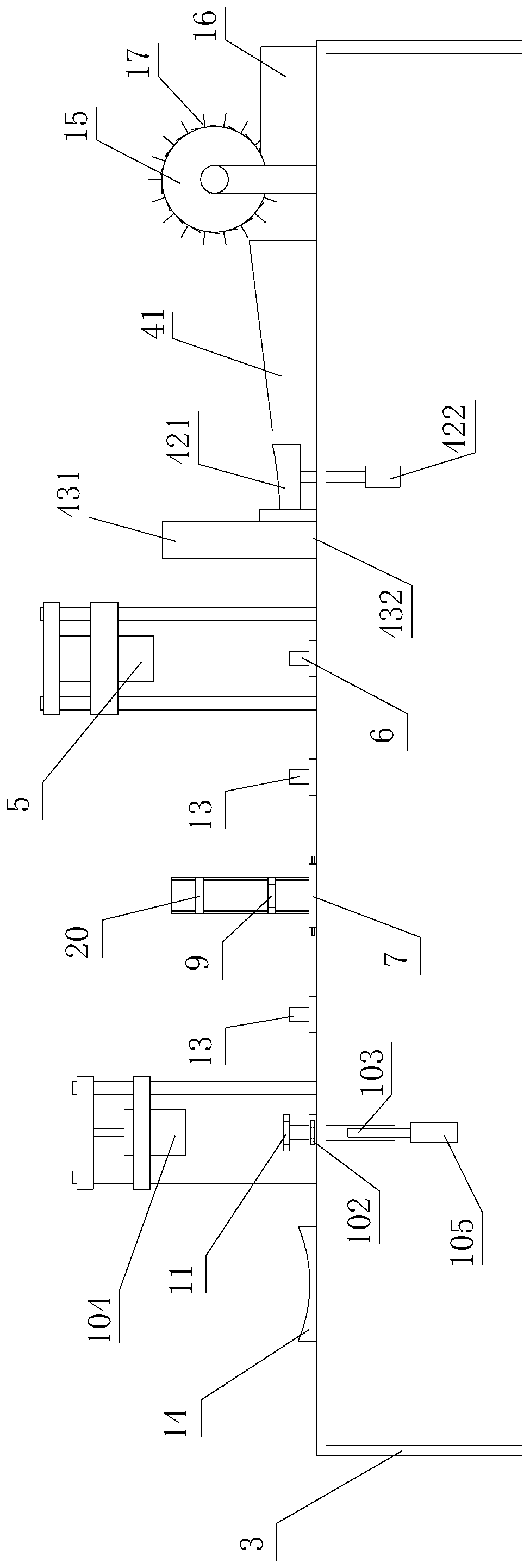
The invention discloses automatic stamping equipment for an air cylinder sleeve and relates to the technical field of lifting chair manufacturing. The automatic stamping equipment comprises a rack, afeeding machine, a necking machine for necking the first end of a raw pipe, a first positioning tank for containing the raw pipe in cooperation with the necking machine, a pressing machine for pressing a concave portion on the circumferential side face of the second end of the raw pipe, a second positioning tank for fixing the raw pipe in cooperation with the pressing machine, a gasket assemblingmachine for conveying and mounting a sealing gasket in the necked first end of the raw pipe, a third positioning tank for fixing the raw pipe in cooperation with the gasket assembling machine, and a mechanical arm for clamping the raw pipe for transportation. The feeding machine comprises an inclined plate, a jacking device arranged on the side of the lower end of the inclined plate, and a turnover mechanism arranged on the side, opposite to the side where the inclined plate is located, of the jacking device. According to the arrangement, the problem that a machining and producing mode of theair cylinder sleeve in the prior art is low in efficiency and high in labor cost is solved.

Description

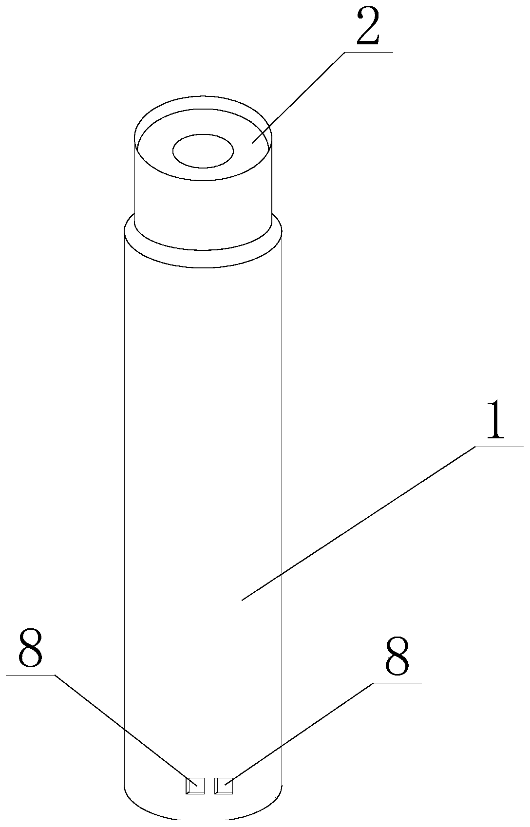
technical field [0001] The invention relates to the technical field of lift chair manufacture, and more specifically, relates to an automatic punching equipment for a cylinder sleeve. Background technique [0002] The lift chair is a kind of seat commonly used in daily life. Among them, the air lift chair with relatively simple structure and low manufacturing cost is widely used. Because its use and maintenance cost is basically zero, it is currently put into production as a mainstream lift chair product. in use. The lifting mechanism of the pneumatic chair mainly includes the cylinder, and the production of the cylinder sleeve needs to go through three processes of reducing the diameter, stamping, punching, and installing the sealing gasket. Please refer to figure 1 For the cylinder sleeve shown in the figure, diameter reduction stamping is to reduce the diameter of one end of the raw material tube of the sleeve, and punching is to process a depression on the other end of ...

Claims


Application Information

Patent Timeline
Patent Type & Authority Applications(China)
IPC IPC(8): B21D22/02B21D41/04B21D43/00B21D43/10B21D43/14B21D45/04B23P19/08B23P19/00
CPCB21D22/02B21D41/04B21D43/006B21D43/105B21D43/145B21D45/04B23P19/001B23P19/006B23P19/08
Inventor 张颢宋元成张启旭
Owner QINGDAO ZEHAO AUTO PARTS
Why Eureka
Try Eureka