Electronic part clamp

A technology of electronic parts and fixtures, which is applied in the field of electronic parts fixtures, can solve the problems of electronic parts clamping damage, single clamping function, etc., and achieve the effect of avoiding clamping damage and avoiding damage

Inactive Publication Date: 2020-03-17
徐州鸿杰电子有限公司
View PDF0 Cites 0 Cited by
  • Summary
  • Abstract
  • Description
  • Claims
  • Application Information

AI Technical Summary

Problems solved by technology

[0002] In the assembly process of electronic products, electronic parts need to be clamped and positioned by fixtures. The fixture structure in the prior art is relatively simple, and most of them only have a single clamping function, and the clamping state depends entirely on the experience of technicians. Sometimes There will be damage to the electronic parts

Method used


Image

  • Electronic part clamp

Examples


Embodiment Construction

[0012] The present invention will be further described below in conjunction with accompanying drawing.

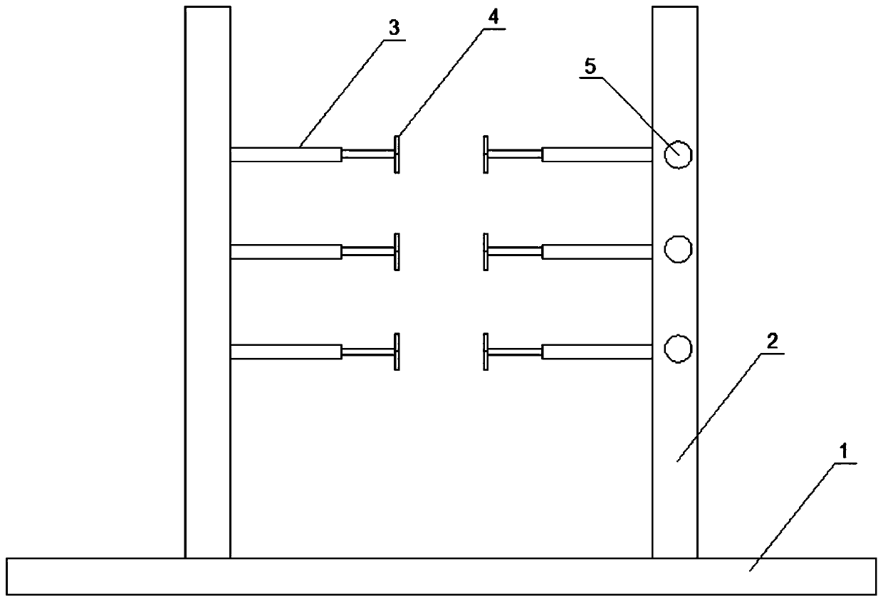
[0013] like figure 1 As shown, a fixture for electronic parts includes a base plate 1 and two uprights 2 fixedly connected to the left and right sides of the upper portion of the base plate 1, and also includes multiple pairs of horizontal electric push rods 3 arranged oppositely in the longitudinal direction;

[0014] The rod ends of each pair of horizontal push rods are arranged oppositely, and are fixedly connected with splints 4, and the bases of the rod ends of each pair of horizontal push rods are respectively fixedly connected with the inner surfaces of the two columns 2;

[0015] A pressure sensor is attached to the inner surface of one of the two splints 4 on each pair of horizontal push rods. Each pressure sensor is correspondingly provided with a pressure display instrument 5 , and the pressure display instrument 5 is installed on the column 2 .

[0016] There a...


PUM


Abstract

An electronic part clamp comprises a bottom plate and two stand columns fixedly connected to the left side and the right side of the upper portion of the bottom plate, and further comprises a plurality of pairs of horizontal electric push rods oppositely arranged in the longitudinal direction. The rod ends of each pair of horizontal push rods are oppositely arranged and fixedly connected with clamping plates, and bases at the rod ends of each pair of horizontal push rods are fixedly connected with the inner side faces of the two stand columns respectively. A pressure sensor is installed on theinner side face of one of the two clamping plates on each pair of horizontal push rods in an attached mode, and each pressure sensor is correspondingly provided with a pressure display instrument, wherein the pressure display instruments are installed on the stand columns. The clamp can effectively fix an electronic product part and can prevent the electronic product part from being damaged by clamping.

Description

technical field [0001] The invention relates to a fixture for electronic parts. Background technique [0002] In the assembly process of electronic products, electronic parts need to be clamped and positioned by fixtures. The fixture structure in the prior art is relatively simple, and most of them only have a single clamping function, and the clamping state depends entirely on the experience of technicians. Sometimes There will be a situation where the electronic parts are clamped badly. Contents of the invention [0003] Aiming at the above-mentioned problems in the prior art, the present invention provides an electronic component clamp, which can effectively fix the components of electronic products and prevent the electronic components from being damaged. [0004] The invention provides a fixture for electronic parts, which includes a bottom plate and two upright columns fixedly connected to the left and right sides of the top of the bottom plate, and also includes mu...

Claims


Application Information

Patent Timeline
IPC IPC(8): B25B11/00G01L5/00
CPCB25B11/00G01L5/00
Inventor 张梦雨
Owner 徐州鸿杰电子有限公司
Why Eureka
Try Eureka