Ocean wave observation buoy

A buoy and wave technology, used in buoys, photovoltaic modules, special-purpose ships, etc., can solve the problems of high power consumption, lack of batteries, corrosion of the glass cover of solar panels, etc. simple effect

Active Publication Date: 2020-03-17
NAT UNIV OF DEFENSE TECH
View PDF5 Cites 12 Cited by
  • Summary
  • Abstract
  • Description
  • Claims
  • Application Information

AI Technical Summary

Problems solved by technology

[0006] Among the above-mentioned measurement methods, the buoy-type wave measurement has become more and more accurate today with the GPS positioning becoming more and more accurate. However, in the actual application process, the buoys often float freely without a fixed point. It can be used for reference, but the main factors causing the drift are wind, ocean currents and ebb and flow, the most important of which is the disturbance of the buoy by the wind and ebb and flow. Even in a calm period, the position of the buoy ball is uncertain. It brings a lot of interference to the measurers from the starting point or the center point (for the content of this part, please refer to the technical characteristics and actual measurement analysis of the current ocean wave measurement published by the "Journal of Ocean Technology" in August 2015); To solve this problem, the current common method is to use chains and counterweights on both sides of the buoy to fix them respectively. Although this method can limit the movement of the buoy within a certain range, the accuracy of the test data is still poor. The reason is that the buoy is still free to float and move between the two counterweight cement blocks
[0007] At the same time, there is another major factor that seriously restricts the buoy-type wave-measuring equipment, that is, its built-in GPS positioning device consumes a lot of power during non-stop work, and the usual unattended buoy-type wave-measuring A commonly used solution to the problem is to install several solar panels and corresponding battery packs on the surface of the buoy to realize uninterrupted power supply to the GPS positioning device, but after using it for a period of time, the positioning information of the GPS positioning device will be due to The current is not enough and starts intermittently. Because the battery cannot get enough charging current, this phenomenon is particularly obvious, especially at night. The main reason is that the ocean environment is different from the inland environment. Evaporation on higher temperature solar panels (mainly during the day) will crystallize and attach a layer of salt frost, and this layer of salt frost will seriously corrode the glass cover of the solar panel (see details published in 2010 in " Reliability Analysis of Marine Solar Cells in the Journal of Marine Engineering), if it is not cleared regularly, the uninterrupted work of the GPS positioning device can only be realized by regularly replacing the solar panels, so the current buoy-type wave measuring equipment is limited by the current supply The problem is that it cannot be truly unattended. In addition, the buoy-type wave measuring equipment in the vast sea is often an ideal shelter for seabirds, and a large amount of feces excreted by them will also adhere and solidify on the surface of the solar panels, directly affecting Power supply to battery pack

Method used


Image

  • Ocean wave observation buoy
  • Ocean wave observation buoy
  • Ocean wave observation buoy

Examples


Embodiment Construction

[0024] In order to make the technical means, creative features, goals and effects achieved by the present invention easy to understand, the technical solutions in the embodiments of the present invention will be clearly and completely described below in conjunction with the accompanying drawings in the embodiments of the present invention.

[0025] see Figure 1-5 , the specific implementation mode is implemented by adopting the following technical solutions, which can effectively solve the problems existing in the background technology.

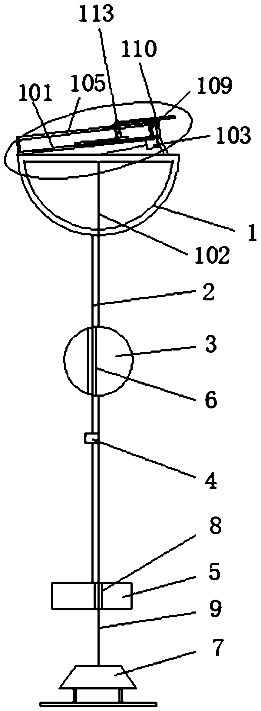
[0026] In order to solve the problems existing in the background technology, it includes a buoy-type wave-measuring ball 1, the interior of the buoy-type wave-measuring ball 1 is sealed with a GPS positioning device, and the surface of the buoy-type wave-measuring ball 1 is also installed with a A solar panel 100 powered by a GPS positioning device; it is characterized in that the buoy-type wave-measuring ball 1 can still completely float on...


PUM


Abstract

The invention discloses an ocean wave observation buoy which comprises a buoy type wave measuring ball (1), wherein a GPS positioning device is installed in the buoy type wave measuring ball (1) in asealed mode, and a solar cell panel (100) for supplying power to the GPS positioning device is further installed on the surface of the buoy type wave measuring ball (1); the buoy type wave measuring ball (1) can still completely float on the ocean surface under the gravity dragging effect of the balancing weight (5); and a first steel cable (2) is fixedly installed in the center of the bottom of the float type wave measuring ball (1), and the lower end of the first steel cable (2) sequentially penetrates through the suspension ball (3) and the positioning ring (4) to be fixedly connected withthe balancing weight (5) into a whole. The ocean wave observation buoy is simple in structure, can guarantee that the float type wave measuring ball can be accurately reset when the wind is flat and quiet, and can eradicate the phenomenon that the float type wave measuring ball drifts freely, and an observer can accurately find the starting point or the middle point of the float type wave measuring ball.

Description

technical field [0001] The invention relates to research equipment related to ocean surges, in particular to an ocean wave observation buoy. Background technique [0002] Waves are essential basic data in marine scientific research and marine engineering design and construction. Aiming at the collection of this important data, a variety of ocean wave detection instruments have appeared at home and abroad; [0003] 1. The pressure wave measuring instrument, in short, uses the underwater high-precision pressure sensor to measure the pressure change caused by the wave movement. This is the most traditional measurement method at present, so as to obtain the parameters related to the wave height. ; [0004] 2. Acoustic wave measuring equipment, which uses underwater acoustic pulses to measure the velocity of the flow or the distance to the water surface; [0005] 3. Buoy-type wave measurement. It should be noted that there are currently two types of wave measurement buoys. One ...

Claims


Application Information

Patent Timeline
Patent Type & Authority Applications(China)
IPC IPC(8): B63B22/00B63B22/20H02S20/00H02S40/10
CPCB63B22/00B63B22/20B63B2022/006H02S20/00H02S40/10Y02E10/50
Inventor 毛科峰陈希李妍郭海龙宋新新杜辉刘科峰陈捷
Owner NAT UNIV OF DEFENSE TECH
Why Eureka
Try Eureka