Novel bearing retainer

A technology for bearing cages and cages, which is applied to bearings, bearing components, liquid cushion bearings, etc., can solve the problems of improving the running accuracy and quality of bearings, failing to reduce bearing vibration and noise, and failing to reach cages, etc., to achieve improved Running performance, reduction of vibration and noise, effect of reducing vibration and noise

Pending Publication Date: 2020-03-17
武汉恒立特轴承有限公司
View PDF2 Cites 1 Cited by
  • Summary
  • Abstract
  • Description
  • Claims
  • Application Information

AI Technical Summary

Problems solved by technology

None of the above-mentioned cages can suspend the cage on the axis of rotation of the bearing, and have a poor effect on reducing the friction between the guide surface of the cage and the guide surface of the outer ring or inner ring, and cannot reduce the vibration and noise of the bearing and improve the running accuracy of the bearing. and running quality

Method used


Image

  • Novel bearing retainer
  • Novel bearing retainer
  • Novel bearing retainer

Examples


Embodiment 1

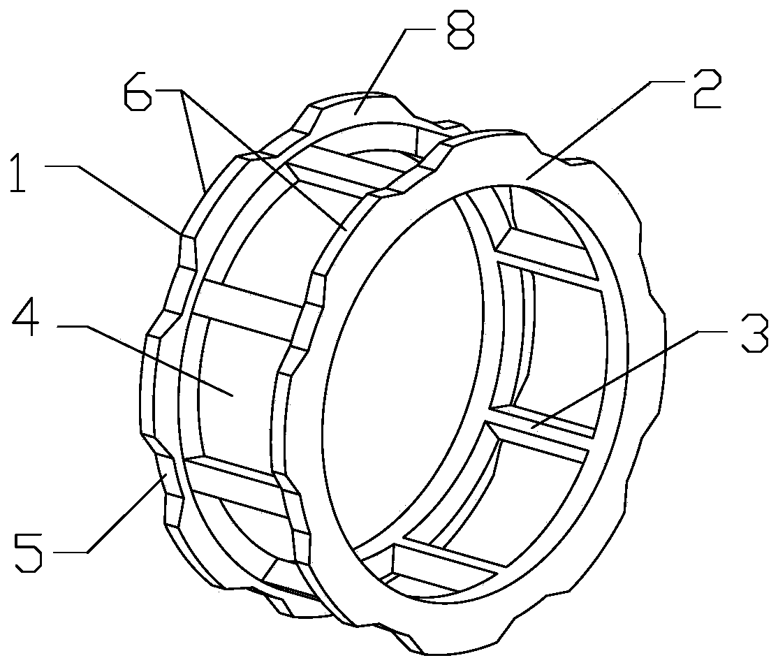
[0035] Embodiment 1 provides an outer guide bearing cage, which is used for bearings with cylindrical rolling elements. The specific structure is as follows: figure 1 and Figure 5 As shown, the cage is a cylindrical structure composed of a left ring 1, a right ring 2, and a plurality of beams 3 connected between the rings on both sides. A square pocket for placing rolling elements is arranged between adjacent beams 3. The hole 4, the left ring 1 and the right ring 2 both protrude toward the outer ring surface of the cylindrical structure to form an outer convex guide part, and an outer guide surface 6 is formed on the outer ring surface of the outer convex guide part. The left side ring 1 and the right side ring 2 of the cage are symmetrically provided with a fluid groove 5 corresponding to the position of each beam 3, and the fluid groove 5 is an axially penetrating outer ring formed on the outer guide surface 6 of the side ring of the cage The inner recesses are evenly dis...

Embodiment 2

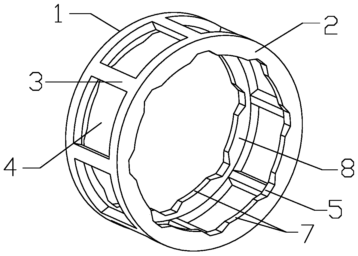
[0037] Embodiment 2 provides an inner guide bearing cage, which is used for bearings with cylindrical rolling elements. The specific structure is as follows: figure 2 and Figure 7 As shown, the cage is a cylindrical structure composed of a left ring 1, a right ring 2 and a plurality of beams 3 connected between the rings on both sides. A square pocket for placing rolling elements is arranged between adjacent beams 3. The hole 4, the left ring 1 and the right ring 2 protrude toward the inner ring surface of the cylindrical structure to form an inner convex guide part, and the inner ring surface of the inner convex guide part forms an inner guide surface 7. A fluid groove 5 is arranged symmetrically at the position corresponding to each beam 3 on the left side ring 1 and the right side ring 2 of the cage. The outer recess of the ring is evenly distributed on the inner ring surface of the side ring along the circumferential direction of the left ring 1 and the right ring 2, an...


PUM


Abstract

The invention provides a novel bearing retainer. The retainer is of a cylinder structure composed of a left side ring, a right side ring and a plurality of cross beams connected between the two side rings. Pockets for placing rolling bodies are arranged between the adjacent cross beams, fluid grooves are symmetrically formed in the positions, corresponding to the cross beams, of the two side ringsof the retainer, the fluid grooves are uniformly distributed on the inner ring surfaces or the outer ring surfaces of the side rings along the circumferential directions of the two side rings, and the opening areas of the fluid grooves are greater than the groove bottom areas of the fluid grooves; when the retainer is guided outwards, the fluid grooves are outer ring inwards-concave parts which are formed on the outer guide face of the retainer side ring and penetrate through the retainer side ring in the axial direction; when the retainer is guided inwards, the fluid grooves are axially-through inner ring outer concave parts formed on the inner guide surface of the retainer side ring. By utilizing the fluid dynamic pressure characteristic, the retainer can suspend at the rotating axis ofthe bearing when the bearing rotates at a high speed, the vibration and noise of the bearing are reduced, the rotating precision is improved, and the service life of the bearing is prolonged.

Description

technical field [0001] The invention relates to the field of bearings, in particular to a novel bearing cage. Background technique [0002] The bearing cage is used to evenly isolate the rolling elements in the bearing, maintain the correct posture and position of the rolling elements during work, and keep the rolling elements in the bearing from falling. It is an important part to ensure the normal operation of the bearing. When the bearing is working, the cage needs to be guided to ensure the concentric rotation of the cage. The guide way of the cage is generally divided into three types: 1. Outer ring guide (abbreviated as outer guide). This structure is characterized by a small gap between the outer diameter of the cage and the inner diameter of the outer ring. The radial positioning of the frame, the two circumferential surfaces with a small gap, are collectively referred to as the guide surface; 2, the inner ring guide (referred to as the inner guide), this structure ...

Claims


Application Information

Patent Timeline
Patent Type & Authority Applications(China)
IPC IPC(8): F16C33/46F16C33/66F16C32/06
CPCF16C32/0629F16C33/46F16C33/6651
Inventor 曹肇伟
Owner 武汉恒立特轴承有限公司
Why Eureka
Try Eureka