
Driving speed change device for agricultural machinery

A technology of speed change device and agricultural machinery, which is applied in the direction of agricultural machinery and implements, transmission device, transmission device parts, etc., can solve the problems such as delay, deformation, even tightness and slippage of driving gearbox.

Active Publication Date: 2020-03-17
铜仁市碧江区农业资源区划研究中心
View PDF3 Cites 0 Cited by
  • Summary
  • Abstract
  • Description
  • Claims
  • Application Information

AI Technical Summary

Problems solved by technology

[0004]When the drive gearbox is adjusted according to the speed from time to time, the conflict between the harvesting equipment and the drive gearbox will be due to the long-term speed adjustment of the gearbox Contact and impact will cause deformation or even looseness, which will easily cause the subsequent drive gearbox to resist, delay, and slip when driving the equipment.

Method used


Image

  • Driving speed change device for agricultural machinery
  • Driving speed change device for agricultural machinery
  • Driving speed change device for agricultural machinery

Examples


Embodiment

[0032] as attached figure 1 to attach Figure 9 Shown:

[0033] The invention provides a drive transmission device for agricultural machinery, the structure of which includes a push rod a1a, a receiving barrel a2a, a harvesting head a3a, a guide body a4a, a booster wheel a5a, a bottom fixing plate a6a, and a drive gearbox a7a.

[0034] The push rod a1a is welded on the outer surface of the bottom solid plate a6a, the receiving tube a2a is installed on the upper surface of the bottom solid plate a6a, the harvesting head a3a is connected with the rotating body a4a, and the booster wheel a5a runs through the Inside the bottom fixing plate a6a, the drive gearbox a7a abuts against the outer surface of the guide body a4a and is movably connected.

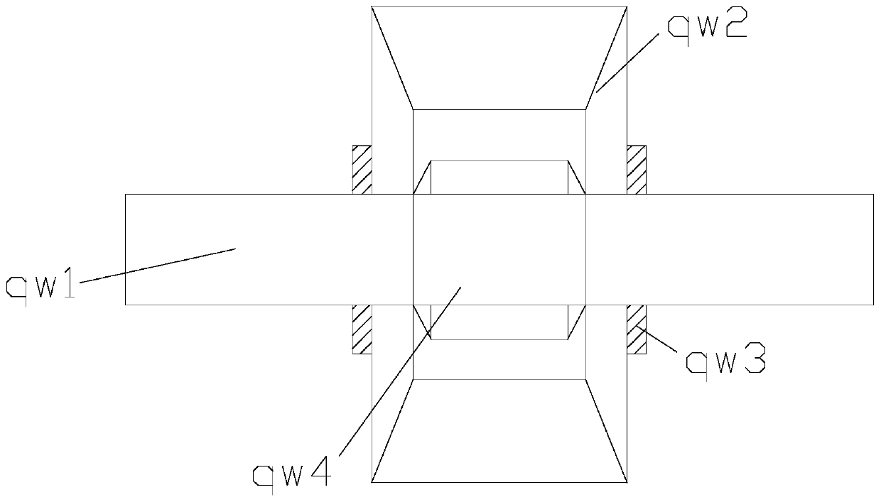
[0035] The drive gearbox a7a includes a middle rod qw1, a transfer box body qw2, an outer limit ring qw3, and a card body qw4. The middle rod qw1 is connected to the card body qw4 and is located on the same axis. The outer limit ring qw...


PUM


Abstract

The invention discloses a driving speed change device for agricultural machinery. The driving speed change device comprises a push rod, a receiving barrel, a harvesting head, a guide revolving body and a boosting wheel, wherein the push rod is welded on the outer surface of a bottom fixed plate; the receiving barrel is arranged on the upper surface of the bottom fixed plate; the guide revolving body is driven to move by a driving transmission box in order to harvest external Chinese chives; a rotary box body inside the driving transmission box is driven to rotate together; the fixing range ofan extension main core is expanded by a surface core; and under the external stress, an internal inclination fixed core fixed by a fixing ball extends by an inclination angle, and an inclination sidedrives an ejector headers against the inclination fixed core at certain hardness, so that an outer layer is subjected to certain inclination guide fixing. Contact force is uniformly born by a spreading side and a protection rubber body to drive a middle fixed column to move, so that the collision force is variable during internal driving speed change. The buffering depth is adjusted according to the collision distance and the force, so that deformation and loosening after long-time collision and contact are prevented.

Description

technical field [0001] The invention belongs to the field of agricultural machinery, and more specifically relates to a drive transmission device for agricultural machinery. Background technique [0002] When the agricultural machinery for harvesting leeks is running, the driving speed of the harvesting needs to adjust the harvesting speed according to the length of the leeks. There will be a fitting joint between the driving gearbox and the harvesting equipment, so that the harvesting equipment can be in time. The gearbox is synchronized according to the adjustment. [0003] Based on the inventor's discovery above, the drive speed change device of existing agricultural machinery mainly has the following deficiencies, such as: [0004] When the drive gearbox is adjusted according to the speed that is sometimes fast and sometimes slow, the conflicting buckle between the harvesting equipment and the drive gearbox will be deformed or even loose due to the long-term speed adjus...

Claims


Application Information

Patent Timeline
IPC IPC(8): F16H35/18F16H35/10F16H57/028A01D45/00A01D69/06
CPCF16H35/18F16H35/10F16H57/028A01D45/00
Inventor 徐守波
Owner 铜仁市碧江区农业资源区划研究中心
Learn More