
Regulator

A regulator and pressure regulating valve technology, applied in the field of regulators, can solve the problems of the valve seat seat 4 falling off and easily falling off, and achieve the effects of eliminating individual differences, high-precision and reliable installation, and excellent wear resistance.

Pending Publication Date: 2020-03-17
NIKKI CO LTD
View PDF18 Cites 0 Cited by
  • Summary
  • Abstract
  • Description
  • Claims
  • Application Information

AI Technical Summary

Problems solved by technology

[0009] However, the following problems also arise: in the case of forming the valve seat portion 4 with an elastic material, it is easy to fall off due to deterioration due to use and the adhesive force generated between the valve seat portion 4 and the pressure regulating valve element 6 . , in addition to being notable when not used for a long time, applying pressure to make the high-pressure fluid recirculate between the valve seat portion 4 and the holding portion 57 during use will also cause the valve seat portion 4 to fall off from the holding portion 57 (refer to Figure 10 )

Method used


Image

  • Regulator
  • Regulator
  • Regulator

Examples


Embodiment Construction

[0064] Hereinafter, modes for implementing the present invention will be described with reference to the drawings.

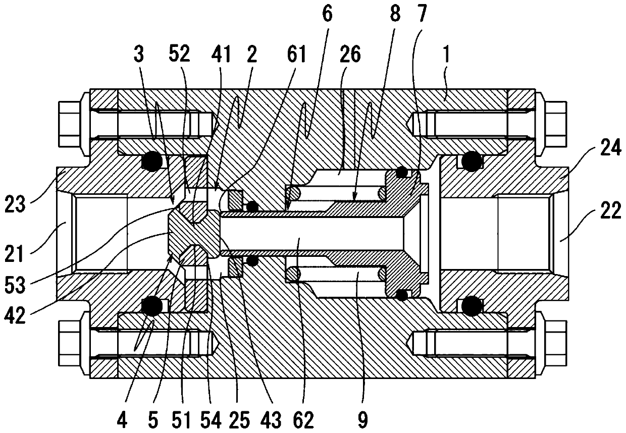
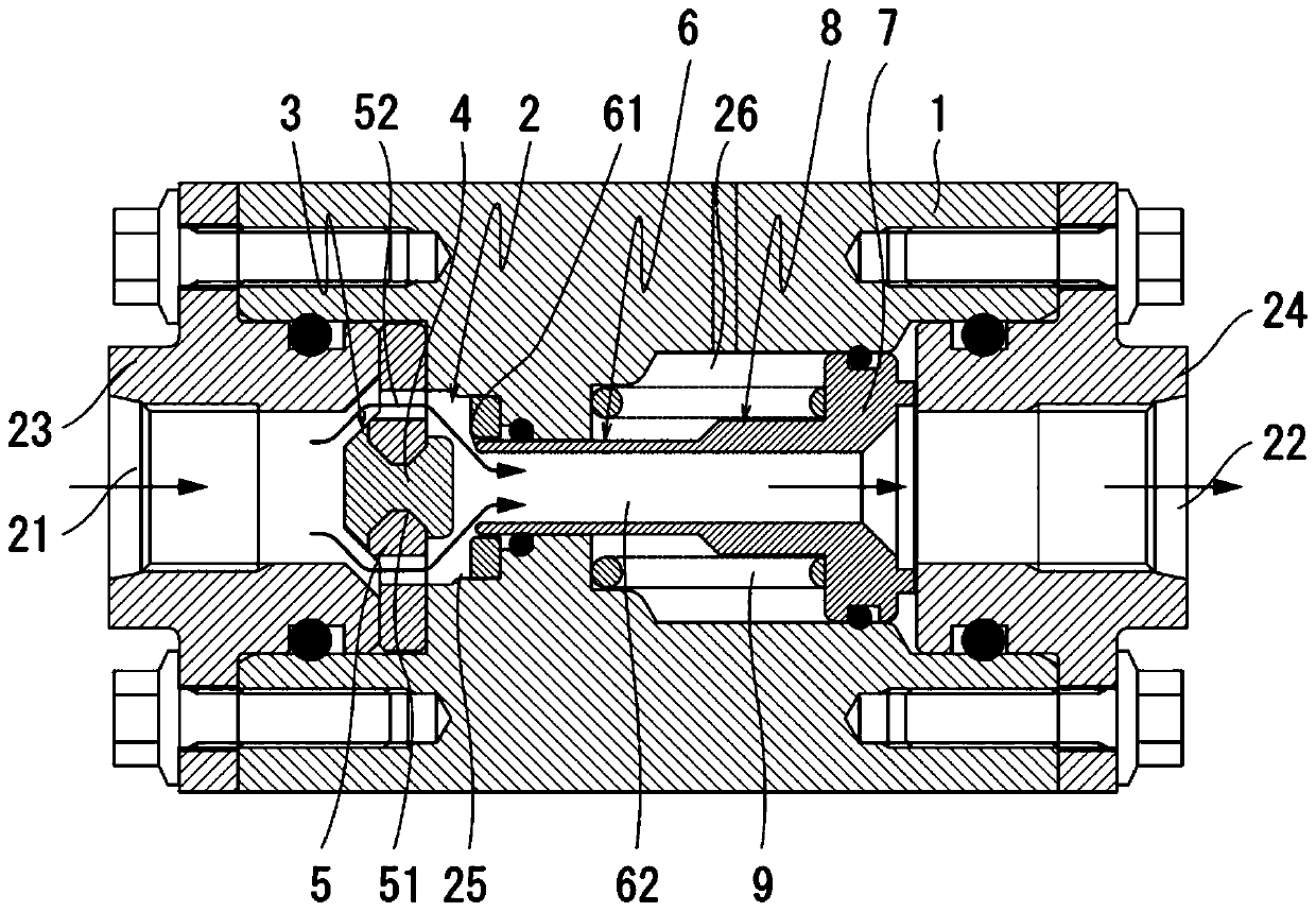
[0065] figure 1 and figure 2 A cross-sectional view showing a preferred embodiment of the present invention, the overall structure is the same as that described above Figure 7 to Figure 10 The conventional examples shown are substantially the same, and detailed descriptions of these configurations are omitted. In addition, the same code|symbol is attached|subjected to the same part as the above-mentioned conventional example, and it demonstrates.

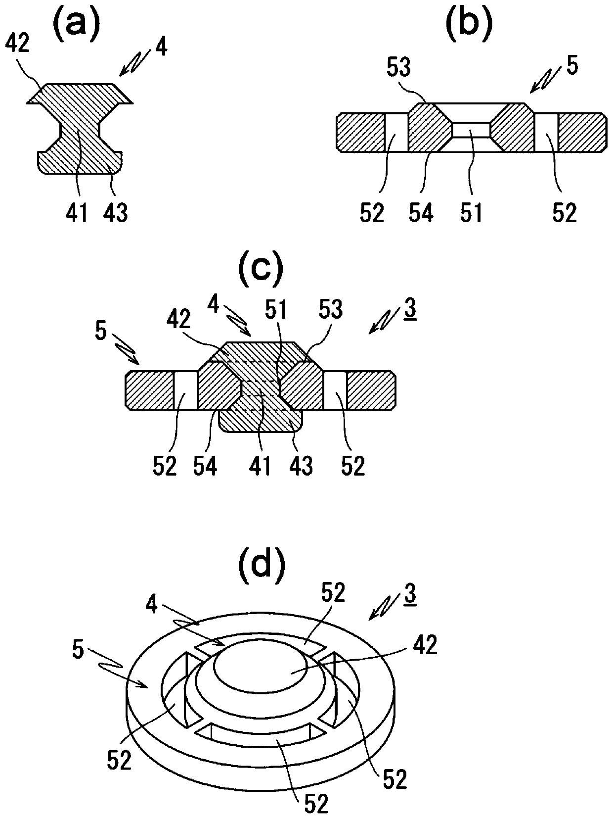
[0066] In addition, the point which is particularly different from the above-mentioned conventional example is the structure of the valve seat 3 . Such as image 3 As shown, the valve seat portion 4 of the valve seat 3 in this embodiment is composed of a shaft body 41, a locking body 42, and a valve seat portion main body 43. The shaft body 41 is inserted into a holding portion 51, and the holding portion 51 I...


PUM


Abstract

A regulator including a valve seat that can be accurately attached without a separate attachment component and has not fear of coming-off during use is provided. A valve seat unit (3) includes a valveseat (4) and a valve seat holding member (5) which are integrally formed by insert molding. The valve seat (4) includes a shaft body (41), a locking body (42), and a valve seat main body (43) which are integrally formed. The shaft body (41) is fitted into a holding part (51) which is a through hole having openings exposed on a side face (53) of the valve seat holding member (5) on an introductionport (21) side and a side face (54) on a pressure regulating chamber (25) side. The locking body (42) is joined and disposed along the side face (53) of the valve seat holding member (5) on the introduction port (21) side and has a larger diameter than the shaft body (41). The valve seat main body (43) is joined and disposed along the side face (54) of the valve seat holding member (5) on the pressure regulating chamber (25) side and has a larger diameter than the shaft body (41).

Description

technical field [0001] The present invention relates to a regulator used for depressurizing a high-pressure fluid to a desired pressure. Background technique [0002] For example, as proposed in Japanese Patent Application Laid-Open No. 52-92436, there is a conventionally known regulator that controls the flow rate of high-pressure fluid by using the pressure fluctuation in the pressure regulating chamber to open and close the pressure regulating valve through the piston. The device is used, for example, as a pressure regulator or the like when high-pressure fuel such as CNG stored in a fuel tank is supplied to an engine. [0003] Figure 7 An example of the above-mentioned conventional regulator is shown, and one opening end of the cylindrical passage 2 formed through the main body 1 is used as the inlet port 21 for the high-pressure fluid, and the other opening end is used as the inlet port 21 for the depressurized fluid. In the outlet 22, an inlet mouth 23 for airtightly...

Claims


Application Information

Patent Timeline
Patent Type & Authority Applications(China)
IPC IPC(8): F16K1/42F16K1/38F16K25/00
CPCF16K1/427F16K1/38F16K25/005F16K1/123F16K1/42F02M21/0239Y02T10/30G05D16/103G05D16/10
Inventor 末永直也
Owner NIKKI CO LTD
Learn More