
Magnetic-head supporting element mfg. method

一种支持元件、磁头的技术,应用在支持头、头的流体动力学间距、记录头的配置/安装等方向,能够解决FPC剥落、承载梁或柔性元件机械损害、拉长等问题

Inactive Publication Date: 2006-07-12
TDK CORPARATION
View PDF0 Cites 0 Cited by
  • Summary
  • Abstract
  • Description
  • Claims
  • Application Information

AI Technical Summary

Problems solved by technology

However, in this case, the head supporting element subjected to gram load molding is elongated by applying mechanical coercive force, so there is mechanical damage to the load beam or flexible element
[0009] Also, when the FPC is fixed on the head support member subjected to gram load molding, at the bent portion of the load beam and its periphery, the performance of the FPC adhered to the load beam is degraded and peeling of the FPC may be caused.

Method used


Image

  • Magnetic-head supporting element mfg. method
  • Magnetic-head supporting element mfg. method
  • Magnetic-head supporting element mfg. method

Examples


Embodiment Construction

[0030] Detailed Description of Preferred Embodiments

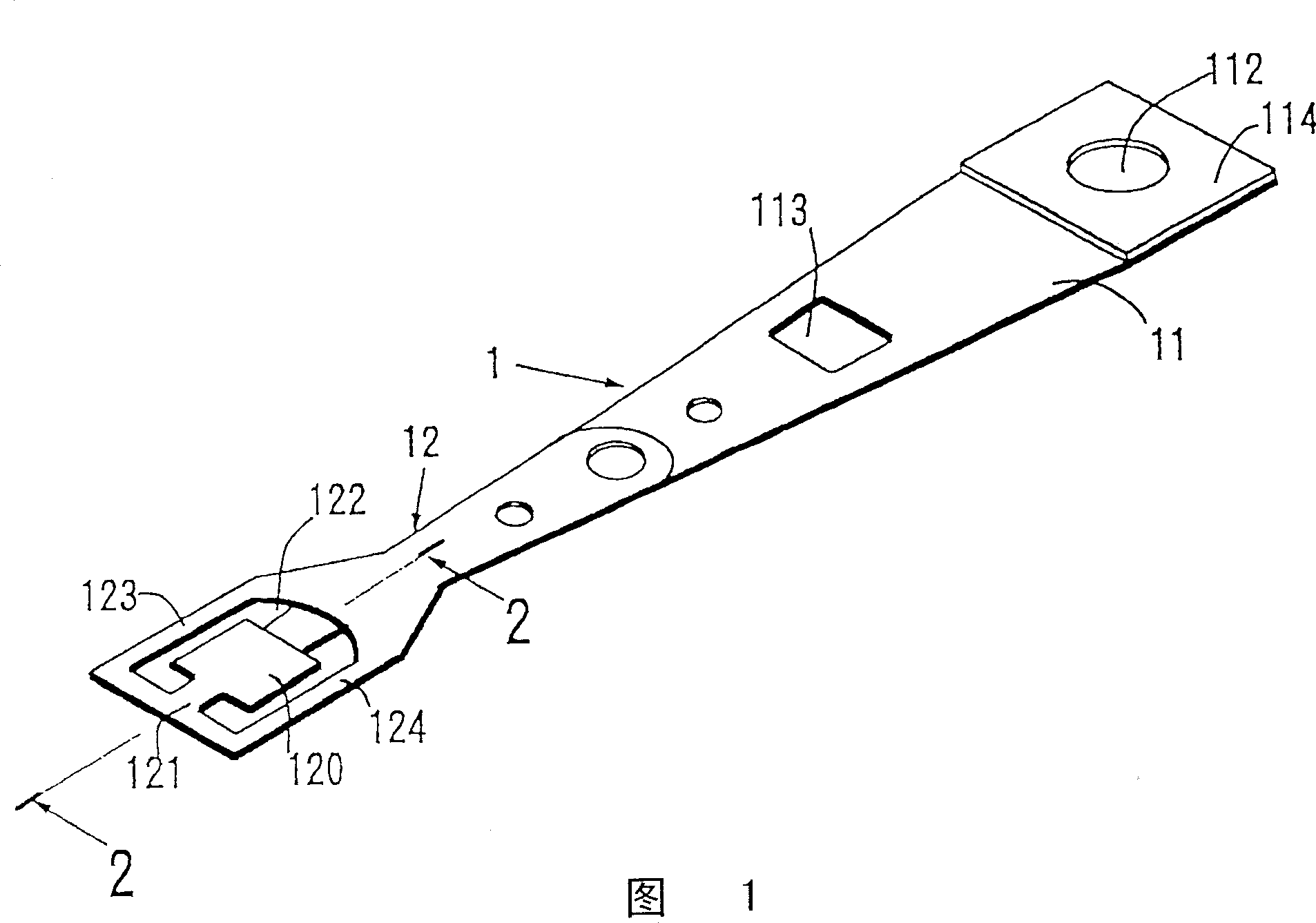
[0031] Figure 1 is a perspective view of a magnetic head supporting member constituting an object to which the manufacturing method of the present invention is applied, and figure 2 is an enlarged partial cross-sectional view taken along line 2-2 of FIG. 1 .

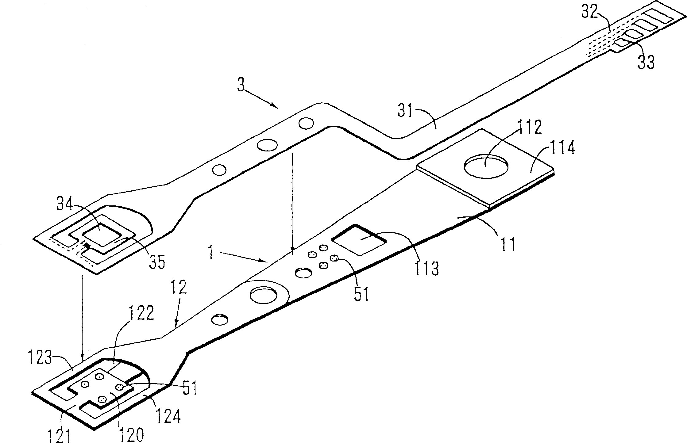
[0032] A magnetic head supporting element 1 includes a load beam 11 and a flexible element 12 . The load beam 11 is integrally formed in the shape of a flat plate, and does not undergo bending associated with an inclination angle. The magnetic head supporting member 1 is provided by the magnetic head supporting member manufacturer in the state of the flat plate shape.

[0033] The load beam 11 is provided with a protruding portion 111 near a free end on an axis in the longitudinal direction passing through the center of the end (see figure 2 ). The load beam 11 is provided with a base portion 114 (see figure 2 ), and a positioning hole 112 is provided substantia...


PUM


Abstract

A fabricating method effective in affixing FPC with high accuracy, simplifying a supporting mechanism of a head supporting member, avoiding mechanical damage to a load beam or a flexible member and promoting performance of adhering FPC to the load beam. Before bending a load beam (11) included in a head supporting member (1), FPC is affxed on a face of the head supporting member (1). Thereafter, the load beam (11) is bent.

Description

technical field [0001] The present invention relates to a method of manufacturing a magnetic head support member. Background of the invention [0002] According to the floating magnetic disk device, a structure has been adopted for many years in which a twisted wire pair is fixed together with a head supporting member, and the twisted wire pair is connected to a wire fixed to the head supporting member by means of laser welding or the like. On the output electrode (flange) of a magnetic head, however, with the miniaturization of the magnetic head structure and the reduction of the floating amount of the magnetic head, high-precision weight balance is required, so a magnetic head device integrated with a circuit forms the mainstream. [0003] In addition, in recent years, it has been simplified to implement an FPC-attached type magnetic head device, in which the circuit is separately manufactured as a flexible printed circuit board (hereinafter referred to as FPC), and the FP...

Claims


Application Information

Patent Timeline
Patent Type & Authority Patents(China)
IPC IPC(8): G11B5/48G11B5/60G11B21/21
CPCY10T29/49128G11B5/486Y10T29/49027Y10T29/49025
Inventor 村松重雄山口哲
Owner TDK CORPARATION
Learn More