
Cab for work machine

A work machine and cab technology, applied in the field of work machine cabs, can solve problems such as difficulty in ensuring vertical and horizontal accuracy

Inactive Publication Date: 2011-05-25
KOMATSU LTD
View PDF7 Cites 0 Cited by
  • Summary
  • Abstract
  • Description
  • Claims
  • Application Information

AI Technical Summary

Problems solved by technology

[0009] However, in the installation structure of the guide rails described in Patent Document 1 and Patent Document 2, since the guide rails are directly installed relative to the steel pipe member constituting the frame body, in the sliding opening and closing mechanism, when the window frame In the case of a structure that is stored on the top surface from the front of the cab, it is necessary to arrange a rail member having a vertical portion along the front of the cab and a horizontal portion along the top surface, so it is difficult to ensure vertical , the problem of horizontal accuracy

Method used


Image

  • Cab for work machine
  • Cab for work machine
  • Cab for work machine

Examples


Embodiment Construction

[0049] Embodiments of the present invention will be described below in conjunction with the accompanying drawings.

[0050] (1) Overall structure

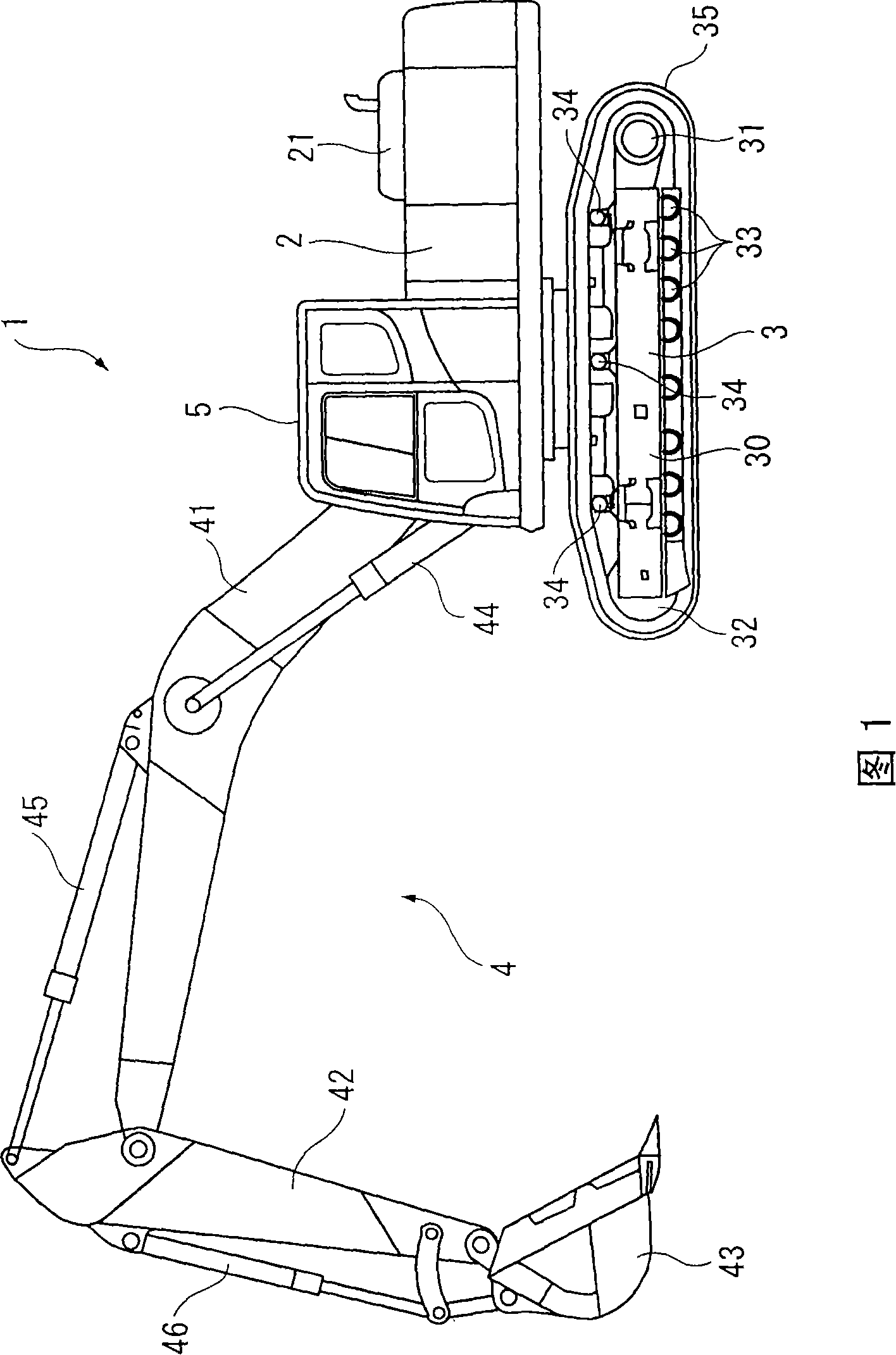
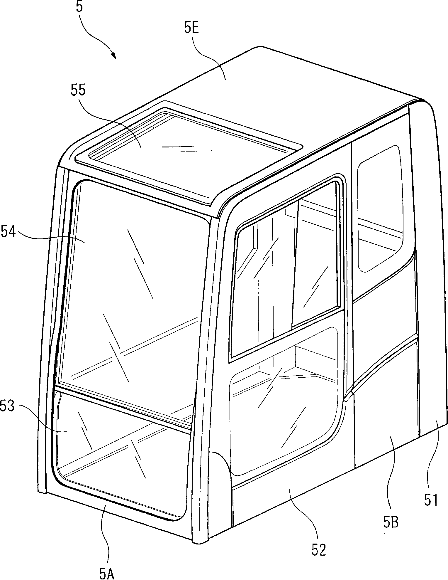
[0051] FIG. 1 shows a hydraulic excavator 1 as a work machine according to an embodiment of the present invention. This hydraulic excavator 1 is configured to include a vehicle body 2 , a traveling device 3 , a work machine 4 , and a cab 5 for the work machine.

[0052] The vehicle main body 2 is equipped with a work machine 4 , a work machine cab 5 , an engine 21 , and a hydraulic circuit driven by the engine 21 (not shown in the figure), the work machine 4 is provided on the front side of the vehicle, and the work machine is provided approximately in the center of the vehicle. The machine cab 5 is provided with an engine 21 on the rear side of the vehicle.

[0053]The traveling device 3 is provided at the lower portion of the vehicle body 2, and supports the vehicle body 2 in the horizontal direction to ensure its free rotation...


PUM


Abstract

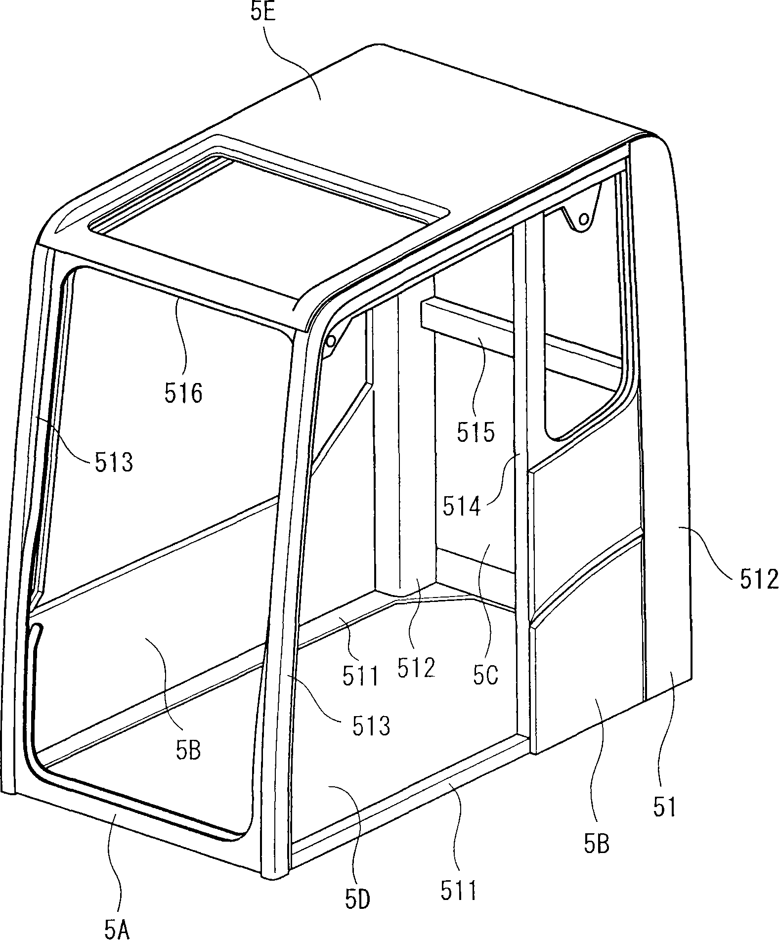
A cab for a work machine formed in a box shape having a front face part, a rear face part, right and left side-face parts, a floor face part, and a roof face part and allowing an operator to operate the work machine to board therein. The cab comprises a frame body having a pair of rear face structural members supporting the rear face part and a pair of side face structural members vertically installed on the floor face part at its front face side both ends, bent along the front face part and the roof face part, and connected to the upper ends of the rear face structural members, a pair of rail members fixed to the pair of side face structural members so that grooves face each other and having vertical parts along the front face part and horizontal parts along the roof face part, and a rectangular window frame body slidably fitted to the grooves of the pair of rail members and stored in the front face part or the roof face part. The vertical parts of the rail members are directly fixedto the side face structural members, and the horizontal parts of the rail members are fixed to the side face structural members through intermediate members.

Description

technical field [0001] The present invention relates to a cab for a working machine on which an operator who operates the working machine rides. Background technique [0002] A working machine such as a hydraulic excavator or a bulldozer is configured to include: a vehicle body provided with a traveling device; a working machine installed on the vehicle body; Cab for work machinery. [0003] The operating machine cab is composed of a frame body formed by welding the ends of a plurality of steel pipe members and a sheet member provided to cover the side surfaces of the frame body. The rigidity of the cab is determined by the welded steel pipe members. The framework made of components is guaranteed. On the other hand, a window frame or the like is attached to such a working machine cab, and the window frame or the like is provided with a window glass or the like. [0004] As opening and closing mechanisms for window frames, doors, etc., there are also opening and closing me...

Claims


Application Information

Patent Timeline
Patent Type & Authority Patents(China)
IPC IPC(8): B62D25/08B60J1/04B60J1/00E02F9/16
CPCB62D33/0617E02F9/163B60J1/04B60J1/004B62D25/08E02F9/16B60J1/00
Inventor 矢野巧造伊藤达志
Owner KOMATSU LTD
Learn More