Photovoltaic cell panel with sunny area convenient to adjust

A photovoltaic cell panel and area technology, applied in photovoltaic power generation, photovoltaic modules, solar thermal power generation and other directions, can solve the problem of inconvenient sunshine area, and achieve the effect of simple structure, convenient use and increasing light receiving area.

Active Publication Date: 2020-03-17
YANGZHOU XINJING PHOTOVOLTAIC TECH
View PDF6 Cites 4 Cited by
  • Summary
  • Abstract
  • Description
  • Claims
  • Application Information

AI Technical Summary

Problems solved by technology

[0003] The purpose of the present invention is to provide a photovoltaic cell panel that is easy to adjust the sunny area, so as

Method used


Image

  • Photovoltaic cell panel with sunny area convenient to adjust
  • Photovoltaic cell panel with sunny area convenient to adjust
  • Photovoltaic cell panel with sunny area convenient to adjust

Examples


Embodiment 1

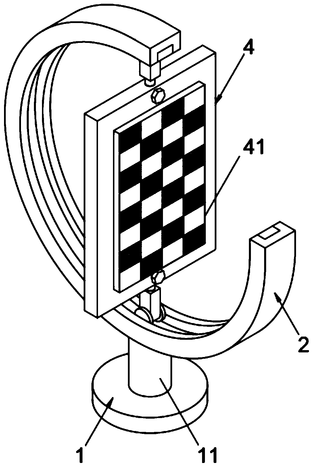
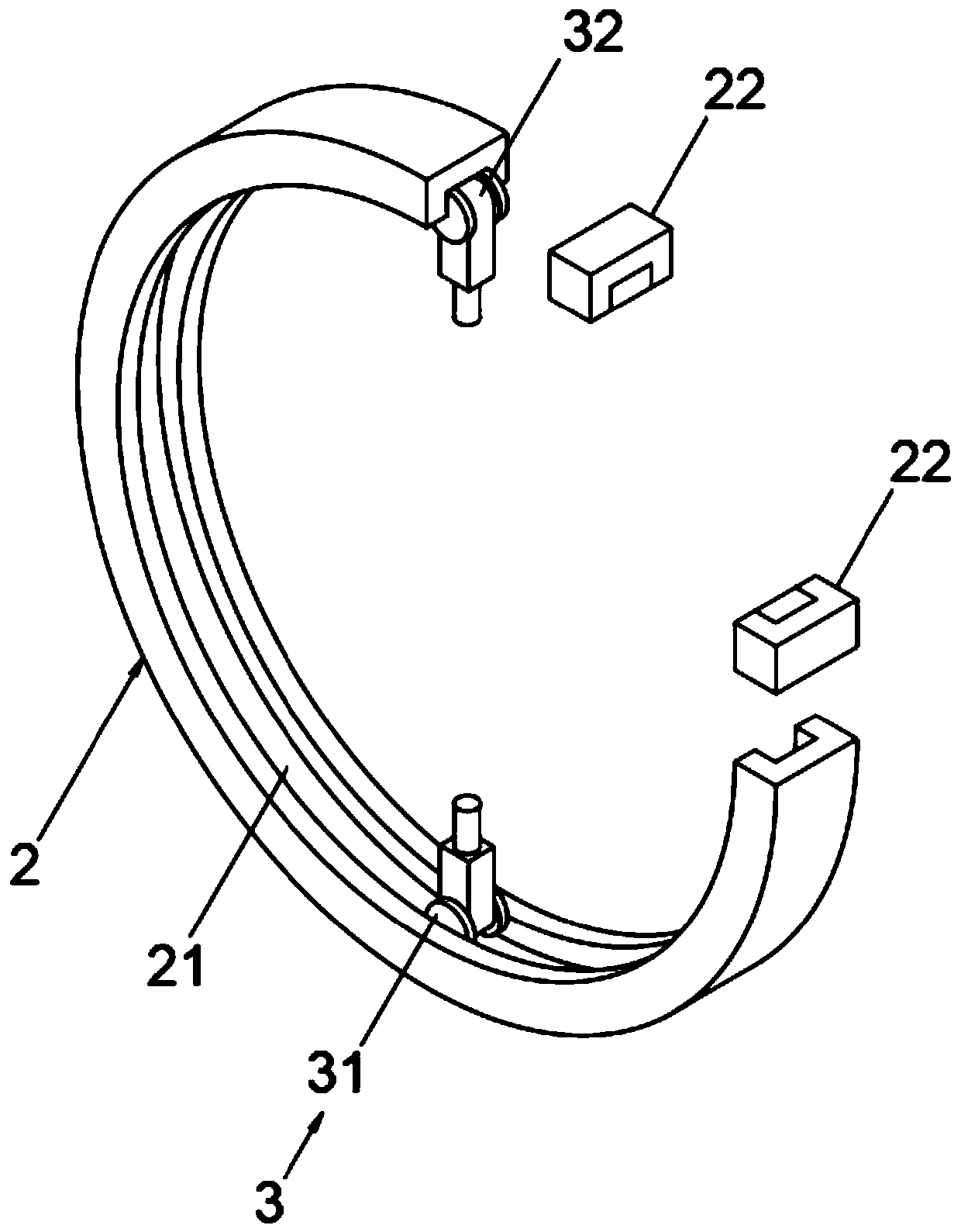
[0025] A photovoltaic panel that facilitates adjustment of the sunny area, such as Figure 1-4 As shown, including the base 1, the upper surface of the base 1 is tightly welded with a pillar 11, and the top of the pillar 11 is tightly welded with an annular slide rail 2, and the inner wall of the annular slide rail 2 is provided with a slideway 21, and there are two slideways 21 The adjustment device 3 is provided with a fixing plate 4 between the two adjusting devices 3 , the outer surface of the fixing plate 4 is installed with a photovoltaic cell panel 41 , and the upper and lower ends of the fixing plate 4 are provided with slots 42 .

[0026] In this embodiment, the fixing plate 4 and the photovoltaic panel 41 are fixedly connected by bolts.

[0027] In this embodiment, the base 1, the annular slide rail 2 and the fixing plate 4 are all made of stainless steel, which has good wear resistance and corrosion resistance, and has the advantages of stable structure and low cost...

Embodiment 2

[0035] As a preferred embodiment of the present invention, such as Figure 5 As shown, the upper and lower ends of the outer surface of the fixing plate 4 are provided with screw holes 43 , the screw holes 43 pass through the fixing plate 4 and communicate with the slots 42 , and the screw holes 43 are provided with bolts 431 .

[0036] The diameter of the bolt 431 matches the diameter of the screw hole 43, and the bolt 431 is threadedly connected with the fixed plate 4 through the screw hole 43. In this embodiment, the diameter of the screw hole 43 is preferably 3 cm, which is convenient for screwing into the slot 42 by the bolt 431 Inside, the bolt 431 locks the latch 322 in the slot 42 to prevent the fixed plate 4 from shaking after turning a certain angle.

[0037] When the photovoltaic battery panel of the present invention is convenient to adjust the sunny area, two adjustment devices 3 are arranged in the slideway 21 on the annular slide rail 2, and a fixing plate 4 is ...


PUM


Abstract

The invention relates to the technical field of photovoltaic cells. The invention relates to a photovoltaic cell panel, in particular to a photovoltaic cell panel convenient for adjusting sunny area.The device comprises a base, a supporting column is tightly welded to the upper surface of the base, an annular sliding rail is tightly welded to the top end of the supporting column, a sliding way isarranged on the inner wall of the annular sliding rail, two adjusting devices are arranged in the sliding way, a fixing plate is arranged between the two adjusting devices, a photovoltaic cell panelis installed on the outer surface of the fixing plate, and inserting grooves are formed in the upper and lower ends of the fixing plate. According to the photovoltaic cell panel convenient for adjusting the sunny area, the sunny area is adjustable; the included angle between the photovoltaic cell panel and the horizontal plane can be changed through the adjusting device; meanwhile, certain friction force exists between the rubber wheel and the inner wall of the slideway, so that the state can still be kept after the fixed plate rotates by a moving angle, in addition, the two ends of the fixedplate can rotate around the plug pins, the orientation of the photovoltaic cell panel on the fixed plate is conveniently adjusted, the light receiving area is increased, and the problem that the sun facing area of the photovoltaic cell panel is inconvenient to adjust is solved.

Description

technical field [0001] The invention relates to the technical field of photovoltaic cells, in particular to a photovoltaic cell panel that facilitates adjustment of the sunny area. Background technique [0002] Photovoltaic panels are devices that directly or indirectly convert solar radiation into electrical energy through photoelectric or photochemical effects by absorbing sunlight. It is inconvenient to adjust the area of ​​the sun-facing side of the battery panel, which makes the power generation efficiency low and inconvenient to use. In view of this, we propose a photovoltaic panel that facilitates adjustment of the sunny area. Contents of the invention [0003] The object of the present invention is to provide a photovoltaic cell panel that can easily adjust the sunny area, so as to solve the problem that the photovoltaic cell panel is not easy to adjust its sunny area proposed in the background art. [0004] To achieve the above object, the present invention prov...

Claims


Application Information

Patent Timeline
IPC IPC(8): H02S20/30F24S30/48
CPCH02S20/30F24S30/48Y02E10/50
Inventor 陈宝山徐飞李玉芳张立恒李超徐福祥
Owner YANGZHOU XINJING PHOTOVOLTAIC TECH
Why Eureka
Try Eureka