Method for operating an auxiliary system of a motor vehicle

A technology for auxiliary systems and motor vehicles, which is applied in the field of auxiliary systems and can solve problems such as increased weight and manufacturing costs

Active Publication Date: 2022-04-08
AUDI AG
View PDF0 Cites 0 Cited by
  • Summary
  • Abstract
  • Description
  • Claims
  • Application Information

AI Technical Summary

Problems solved by technology

Also increases the weight and manufacturing cost

Method used


Image

  • Method for operating an auxiliary system of a motor vehicle
  • Method for operating an auxiliary system of a motor vehicle
  • Method for operating an auxiliary system of a motor vehicle

Examples


Embodiment Construction

[0048] In the figures, parts corresponding to one another are provided with the same reference numerals.

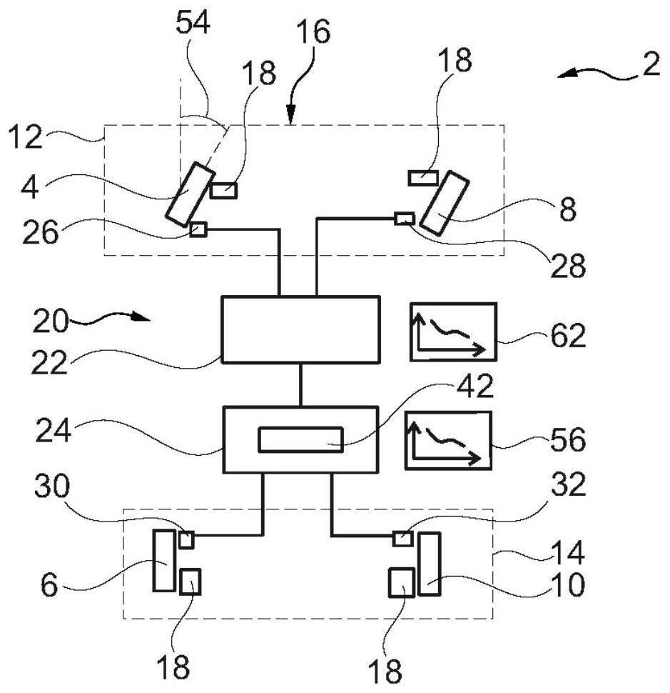
[0049] exist figure 1 A motor vehicle 2 with a first wheel, a second wheel 6 , a third wheel 8 and a fourth wheel 10 is shown schematically in simplified form. The first wheel 4 and the third wheel 8 are assigned to the front axle 12 , and the second wheel 6 and the fourth wheel 10 are assigned to the rear axle 14 . Motor vehicle 2 has only two axles 12 , 14 and is a passenger vehicle (Pkw).

[0050] Motor vehicle 2 also has a braking system 16 with four brakes 18 , one of brakes 18 being assigned to each of wheels 4 , 6 , 8 , 10 . In a corresponding actuation, the rotational speed of the respective wheel 4 , 6 , 8 , 10 is reduced by means of the brake 18 or, if necessary, blocked. The braking system 16 also has an auxiliary system 20 for determining the wheel slip ratios of the first, second, third and fourth wheels 4 , 6 , 8 , 10 . The auxiliary system 20 has a firs...


PUM


Abstract

The invention relates to a method for operating an auxiliary system of a motor vehicle, wherein it is determined whether a fault condition exists in a first control unit or a second control unit; The signal is sent to the first control unit, by means of which the wheel slip of the first wheel is determined from the first sensor signal, and the wheel slip of the second wheel is determined from the second sensor signal; if the first control unit is present If there is a fault situation, the wheel slip ratio of the first wheel is calculated by means of the second sensor signal by means of the second control unit, and the wheel slip ratio of the second wheel is determined from the second sensor signal; if there is a fault of the second control unit In this case, the wheel slip ratio of the first wheel is determined from the first sensor signal by means of the first control unit, and the wheel slip ratio of the second wheel is calculated by means of the first sensor signal.

Description

technical field [0001] The invention relates to a method for operating an auxiliary system of a motor vehicle. The invention also relates to an auxiliary system of a motor vehicle and a motor vehicle. Background technique [0002] Motor vehicles usually have braking systems by means of which the motor vehicle is decelerated. In this case, the brake disc is generally fixed in a rotationally fixed manner indirectly to the wheel of the motor vehicle. At the driver's braking request, the brake pads move towards the brake disc and thus increase the friction, which reduces the rotational speed of the wheels. The driver's brake request is usually detected by means of a brake pedal, which is usually connected hydrodynamically to the brake pads. Furthermore, a brake booster is usually present, so that the brake pedal only has to be actuated with a relatively low force in order to achieve a defined braking effect. [0003] In this case, if the force is too great, the wheels may lo...

Claims


Application Information

Patent Timeline
Patent Type & Authority Patents(China)
IPC IPC(8): B60T8/88B60T8/172
CPCB60T8/885B60T8/172B60T2270/413B60T2240/06B60T8/1761B60T2250/03B60T2270/10B60T17/22
Inventor H·恩斯特
Owner AUDI AG
Why Eureka
Try Eureka