
Clamping tool for crane boom head and boom tail machining

A technology for clamping tooling and cranes, used in metal processing equipment, auxiliary devices, manufacturing tools, etc., can solve the problems of multi-manpower, low production efficiency, unstable welding quality, etc., to improve the degree of automation, improve production efficiency, save money human effect

Pending Publication Date: 2020-03-24
徐州智畅机器人系统有限公司
View PDF0 Cites 1 Cited by
  • Summary
  • Abstract
  • Description
  • Claims
  • Application Information

AI Technical Summary

Problems solved by technology

However, the head, arm and tail of the existing crane arm are manually welded without using fixtures, the welding quality is unstable and more manpower is used, and the production efficiency is low

Method used


Image

  • Clamping tool for crane boom head and boom tail machining
  • Clamping tool for crane boom head and boom tail machining

Examples


Embodiment 1

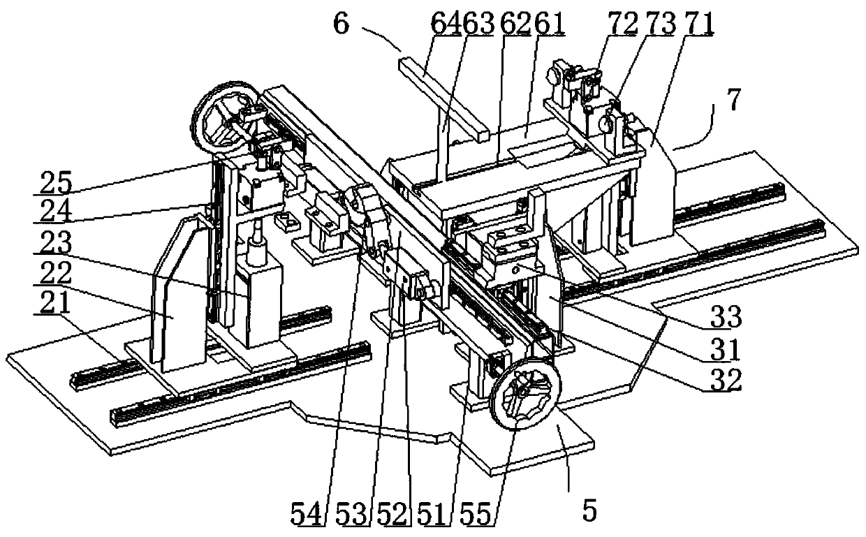
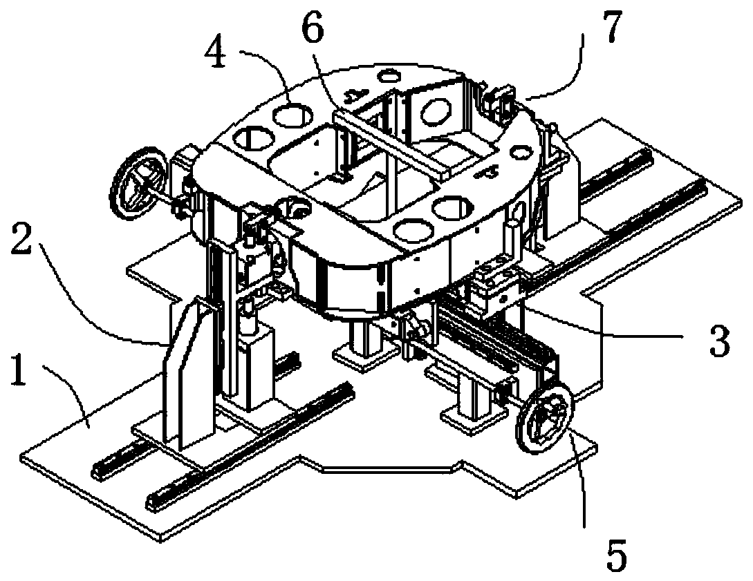
[0029] like figure 2 As shown, the clamping tooling for the processing of the crane arm head and arm tail designed by the present invention includes a tooling base plate 1 and a front clamping mechanism 2 installed on the tooling base plate, a middle centering mechanism 3, a workpiece 4, and a bottom pressing adjustment mechanism 5 , middle pressing bar 6 and rear end clamping mechanism 7, described front end clamping mechanism 2 and rear end clamping mechanism 7 fix the front end and the rear end of workpiece 4, and described middle part centering mechanism 3 adjusts workpiece 4 in tooling The horizontal position on the bottom plate 1, the bottom pressing adjustment mechanism 5 fixes the workpiece 4 through the opening at the bottom of the workpiece, the middle pressing rod 6 realizes the fixing of the upper end surface of the workpiece 4 by pressing down, and the front end clamping mechanism 2. The middle centering mechanism 3, the bottom pressing adjustment mechanism 5, th...

Embodiment 2

[0041] like figure 1 and 2 As shown, the clamping tooling for the processing of the crane arm head and arm tail designed by the present invention includes a tooling base plate 1 and a front clamping mechanism 2 installed on the tooling base plate 1, a middle centering mechanism 3, a workpiece 4, and a bottom pressing adjustment mechanism 5. The central pressing rod 6 and the rear end clamping mechanism 7, the front end clamping mechanism 2 and the rear end clamping mechanism 7 fix the front end and the rear end of the workpiece, and the middle centering mechanism 3 adjusts the workpiece on the tooling base plate 1 The horizontal position of the horizontal position, the middle pressing rod 6 and the bottom adjustment structure are set as reserved installation positions, which are not practically used. Through the setting of this structure, the front clamping mechanism, the middle centering mechanism and the rear clamping mechanism The cooperation between them realizes the clam...


PUM


Abstract

The invention relates to the technical field of industrial equipment and particularly relates to a clamping tool for crane boom head and boom tail machining. The tool comprises a tool bottom plate, afront end clamping mechanism, a middle centering mechanism, a workpiece, a bottom pressing adjusting mechanism, a middle pressing rod and a rear end clamping mechanism, wherein the front end clampingmechanism and the rear end clamping mechanism are used for fixing a front end and a rear end of the workpiece, the middle centering mechanism is used for adjusting the transverse position of the workpiece on the tool bottom plate, the bottom pressing adjusting mechanism is used for fixing the workpiece through an opening at the bottom of the workpiece, and the middle pressing rod is used for fixing an upper end face of the workpiece through downward pressing work. Through cooperation of the front end clamping mechanism, the middle centering mechanism, the bottom pressing adjusting mechanism, the middle pressing rod and the rear end clamping mechanism, clamping of the workpiece is achieved, the clamping tool can be compatible with crane arm heads or arm tails of different specifications andsizes, the clamping tool is convenient and easy to use, and production efficiency is improved.

Description

technical field [0001] The invention relates to the technical field of industrial equipment, in particular to a clamping tool for processing the head and tail of a crane arm. Background technique [0002] A crane refers to a multi-action hoisting machine that lifts vertically and carries heavy objects horizontally within a certain range. Also known as crane, aerial crane, crane. Some working characteristics of lifting equipment are intermittent movements, that is, in a working cycle, the corresponding mechanisms for retrieving, moving, unloading and other actions work alternately. The development and use of cranes in the market are becoming more and more extensive. However, the head, arm and tail of the existing crane arm are manually welded without using fixtures, the welding quality is unstable, more manpower is used, and the production efficiency is low. Contents of the invention [0003] In order to solve the above-mentioned technical problems in the prior art, the p...

Claims


Application Information

Patent Timeline
Patent Type & Authority Applications(China)
IPC IPC(8): B23K37/04
CPCB23K37/0435Y02P70/10
Inventor 孙云权黄兴博罗景龙夏捷侯家伍
Owner 徐州智畅机器人系统有限公司
Learn More