Cylindrical work piece grinding and processing tooling and use method thereof

A grinding and cylindrical technology, applied in the direction of grinding workpiece supports, can solve the problems of increasing manufacturing costs, increasing costs, affecting the hardness of key impact surfaces, etc., and achieving the effect of ensuring grinding accuracy and improving processing yield

Inactive Publication Date: 2012-12-12
YANTAI AIDI PRECISION MASCH CO LTD
View PDF6 Cites 6 Cited by
  • Summary
  • Abstract
  • Description
  • Claims
  • Application Information

AI Technical Summary

Problems solved by technology

After the surface treatment, the workpiece needs to be ground. Generally, there are two methods for the grinding of such workpieces: one is to leave a process table with a center hole at one end of the workpiece, and remove it after all the grinding is completed. The defect of this method is that the surface hardness of the workpiece is increased due to the need for carburizing and quenching before grinding the workpiece, so it is difficult to remove the craft table after grinding, and the piston processed by this process will be scrapped due to The process table will increase a certain cost. The second is that there is no carburized layer on the end face after removing the process table, which affects the hardness of the key impact surface; There is no longer a central hole at the end, so that when entering the carburizing process, the impact surface of the piston can be obtained with a good surface treatment quality, which is very conducive to improving the performance of the piston, but this method is not effective in the subsequent grinding process. It leaves difficulties for the clamping of the workpiece. The method of the prior art is to clamp one end of the workpiece with the chuck of the headstock of the grinding machine, and the tip of the tailstock withstands the other end of the workpiece for grinding
Due to the limitation of the rotation accuracy of the grinding machine headstock, the accuracy of grinding workpieces by this method is not ideal, and it is inconvenient to adjust the grinding allowance. Scrap, which increases manufacturing costs

Method used


Image

  • Cylindrical work piece grinding and processing tooling and use method thereof
  • Cylindrical work piece grinding and processing tooling and use method thereof
  • Cylindrical work piece grinding and processing tooling and use method thereof

Examples


Embodiment Construction

[0030] The principles and features of the present invention are described below in conjunction with the accompanying drawings, and the examples given are only used to explain the present invention, and are not intended to limit the scope of the present invention.

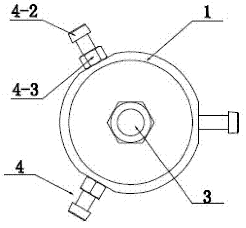
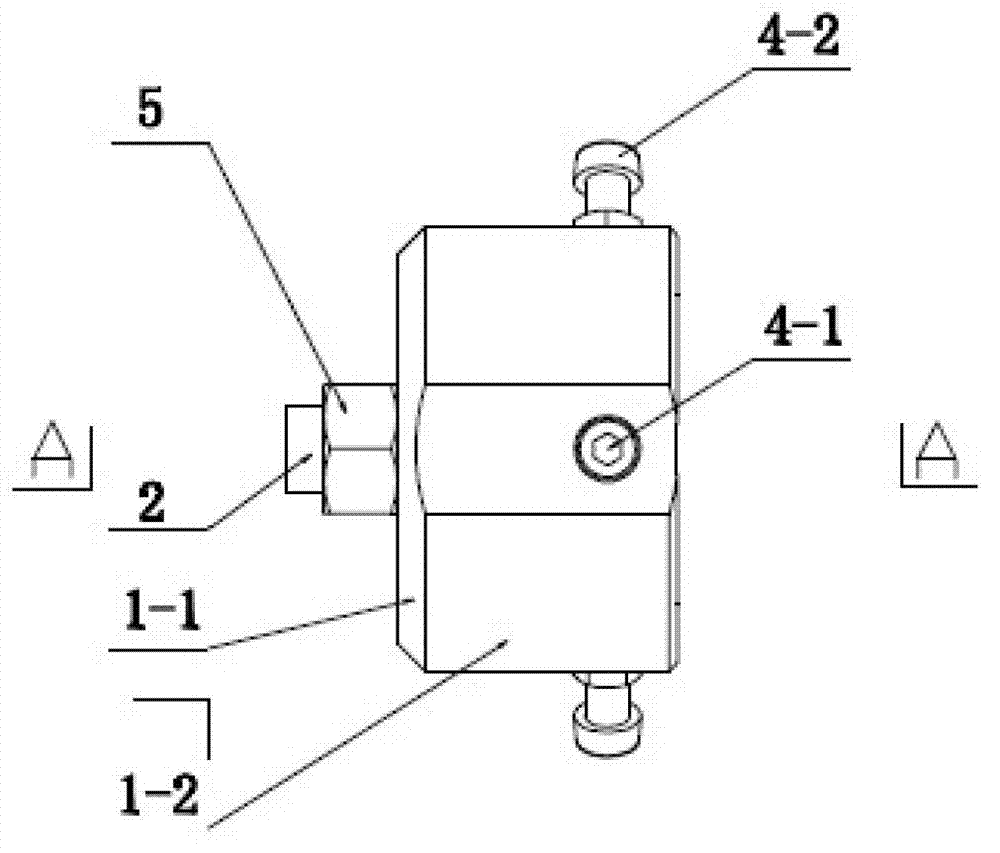
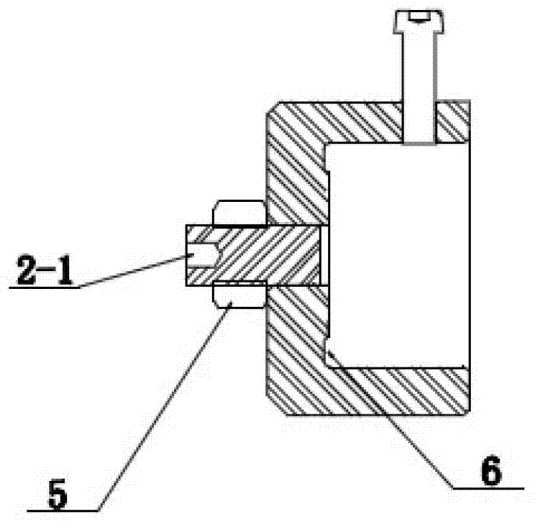
[0031] Such as Figure 1 to Figure 3 As shown, a cylindrical workpiece grinding tooling includes a cylindrical tooling body 1 and a process plug 2, the tooling body 1 includes a cylinder wall 1-2 and a cylinder bottom 1-1, and the cylinder bottom The center of 1-1 is provided with a threaded through hole 3, the process plug 2 is fixed in the threaded through hole 3, the center of the process plug 2 is provided with a central hole 2-1, and the cylinder wall 1- 2 is provided with workpiece position adjustment locking mechanism 4. In actual use, it is necessary to ensure the flatness of the cylinder bottom 1-1 and the perpendicularity of the plane to the axis of the workpiece.

[0032] The workpiece position adjustme...


PUM


Abstract

The invention discloses a cylindrical work piece grinding and processing tooling which is characterized by consisting of a cylindrical tooling body and a process plug head; the tooling body comprises a cylindrical wall and a cylindrical bottom; a threaded through hole is arranged in the center of the cylindrical bottom; the process plug head is fixedly arranged in the threaded through hole; a central hole is arranged in the center of the process plug head; and three sets of work piece position adjusting and locking mechanisms are arranged on the cylindrical wall. The invention also discloses a use method of the tooling. According to the tooling and the use method, the work piece coarse and fine grinding and processing problems that the end of a similar piston is provided with no central hole are fully solved, i.e. the central hole can be removed before the surface of the work piece is strengthened, so that very good hardness and wear resistant performance are realized on the surface treatment on the end surface of the work piece.

Description

technical field [0001] The invention relates to an auxiliary device for grinding a cylindrical workpiece, in particular to a grinding tool for a cylindrical workpiece and a use method thereof. Background technique [0002] In industrial production, in order to improve product precision and surface roughness, it is often necessary to grind cylindrical workpieces on a grinding machine. For ordinary precision requirements or the grinding of cylinders with central holes at both ends, the machining accuracy will not be affected by unreasonable clamping, but some products are limited by the special requirements of the product, and one or both ends of the workpiece It is not allowed to keep the center hole after some processes, which makes subsequent processing difficult. For example, the piston in the hydraulic breaker belongs to this situation. The design and processing quality of the piston determine the performance of the breaker to a great extent. The impact end of the piston...

Claims


Application Information

Patent Timeline
Patent Type & Authority Applications(China)
IPC IPC(8): B24B41/06
Inventor 宋飞宋欧赵卫乐
Owner YANTAI AIDI PRECISION MASCH CO LTD
Why Eureka
Try Eureka