
Tension-free buffer device

A buffering equipment, tension-free technology, applied in the direction of cells, electrolysis process, electrolysis components, etc., can solve the problems of inability to eliminate tension, increased tension of the whole line, poor electroplating, etc., to improve electroplating quality, eliminate tension, and improve production efficiency Effect

Pending Publication Date: 2020-03-24
KUNSHAN YIDING IND TECH CO LTD
View PDF0 Cites 0 Cited by
  • Summary
  • Abstract
  • Description
  • Claims
  • Application Information

AI Technical Summary

Problems solved by technology

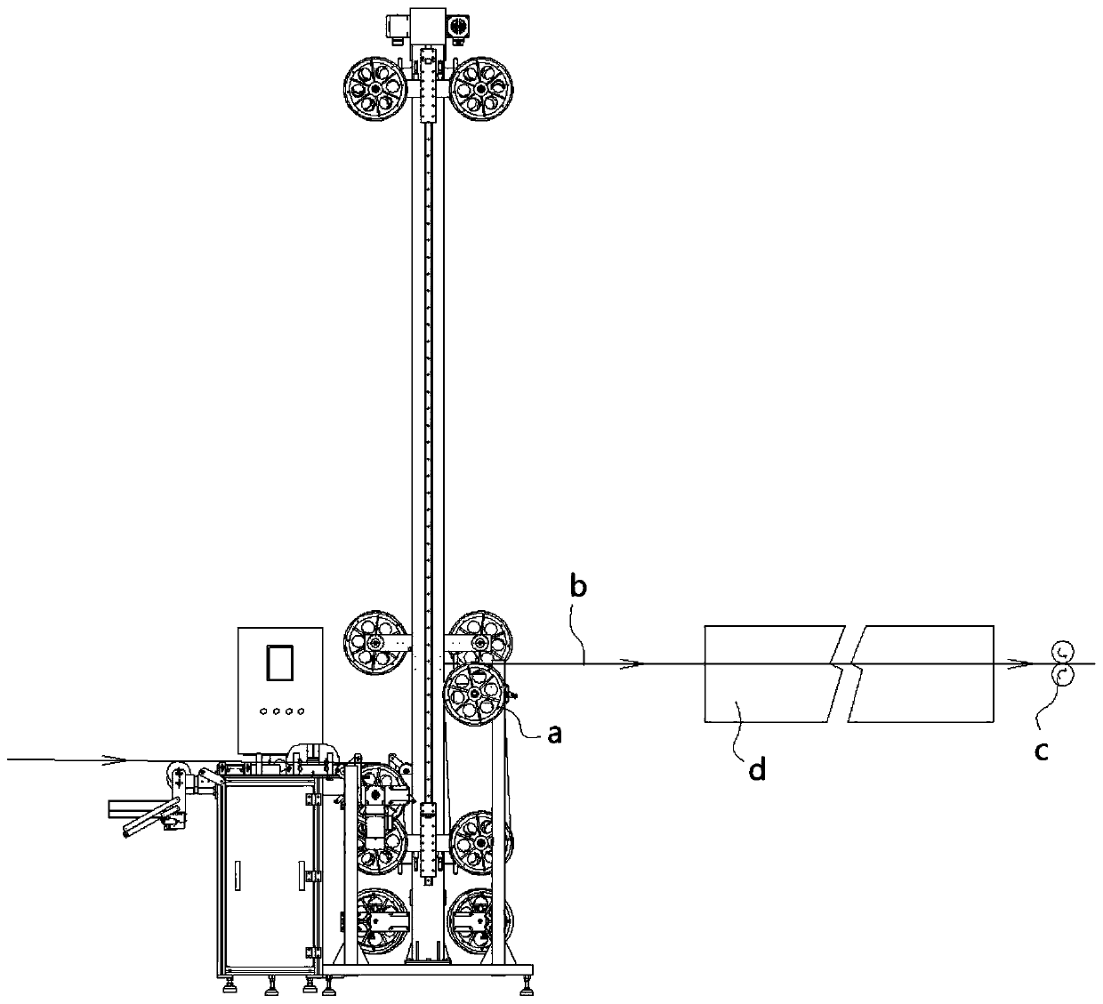
[0003] Existing buffer machines usually reduce the tension of the material belt by adjusting the counterweight or motor torque, but the tension cannot be completely eliminated, which will cause the material belt to have tension when it enters the electroplating tank, and the material belt will be deformed for special products, resulting in Increased tension of the whole line, poor plating and other defects
There is no driving device when the material belt enters the electroplating tank through the existing buffer machine, so the tension accumulated by the material belt through the original buffer machine cannot be eliminated. If the buffer machine is not used, the production efficiency cannot be improved

Method used


Image

  • Tension-free buffer device
  • Tension-free buffer device
  • Tension-free buffer device

Examples


Embodiment Construction

[0031] The following describes in detail the embodiments of the present invention, examples of which are illustrated in the accompanying drawings, wherein the same or similar reference numerals refer to the same or similar elements or elements having the same or similar functions throughout. The embodiments described below with reference to the accompanying drawings are exemplary, only used to explain the present invention, and should not be construed as a limitation of the present invention.

[0032] In the description of the present invention, it should be understood that the terms "center", "longitudinal", "lateral", "length", "width", "thickness", "upper", "lower", "front", " Rear, Left, Right, Vertical, Horizontal, Top, Bottom, Inner, Outer, Clockwise, Counterclockwise, Axial, The orientations or positional relationships indicated by "radial direction", "circumferential direction", etc. are based on the orientations or positional relationships shown in the accompanying dr...


PUM


Abstract

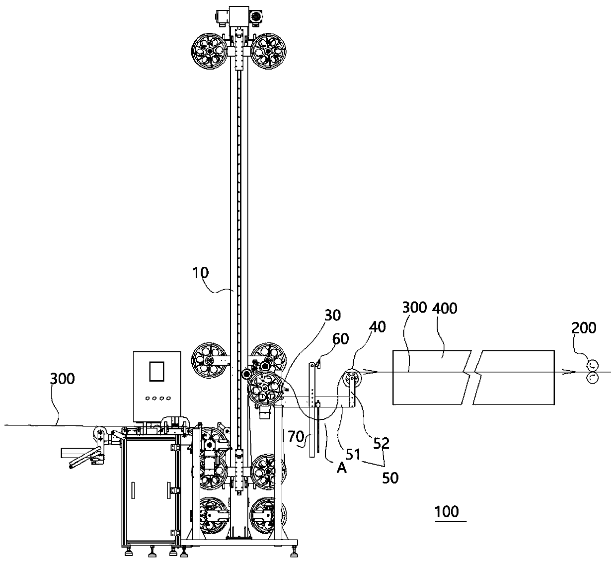
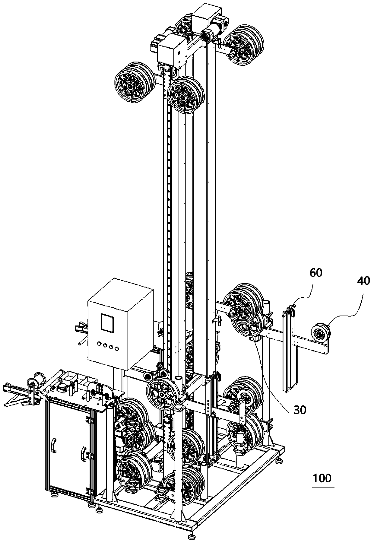
The invention discloses tension-free buffer device which can be used for being matched with a downstream material belt traction part to convey a material belt into an electroplating tank body betweenthe material belt traction part and the tension-free buffer device. The tension-free buffer device comprises a machine body; an input part, which is arranged in the machine body and used for introducing the material belt into the machine body from the upstream; a discharging wheel which is arranged on the machine body and used for outputting the material belt from the machine body; a guiding part,which is spaced to the discharging wheel to form a tension adjusting area, the linear speed of the guiding part being not larger than that of the material belt traction part, the material belt naturally drooping to enter a tension adjusting area after passing through the discharging wheel, and the guiding part receiving the material belt and conveying the material belt and the material belt traction part into the electroplating bath body in a matched mode; and a driving part which can adjust the linear speed of the discharging wheel according to the drooping shape of the material belt in thetension adjusting area. According to the tension-free buffer device, the material belt can enter the electroplating bath body in a loose state, so that the tension of an electroplating line is reduced, the tension is kept absolutely stable, the electroplating quality is improved, and the production efficiency is improved.

Description

technical field [0001] The invention belongs to the technical field of electroplating parts production and conveying, and in particular relates to a tension-free buffer device. Background technique [0002] The electroplating workpiece conveyor can be used to transport and convey the load-carrying equipment for processing workpieces in the electroplating automatic production line. Its mobility and stability directly affect the electroplating production efficiency and the quality of electroplating products. In order to improve the overall production line operation stability, it is necessary to equip electroplating workpieces Conveyor buffer. [0003] The existing buffer machine usually reduces the tension of the material belt by adjusting the counterweight or motor torque, but it cannot completely eliminate the tension, which will cause the material belt to have tension when it enters the electroplating tank. The tension of the whole line is increased, and the defects such a...

Claims


Application Information

Patent Timeline
IPC IPC(8): C25D7/06C25D17/00C25D21/12
CPCC25D7/0621C25D21/12
Inventor 周爱和
Owner KUNSHAN YIDING IND TECH CO LTD
Learn More