Turnout fastener mechanical anti-loosening structure

A technology for fasteners and turnouts, which is applied in the field of mechanical anti-loosening structures of turnout fasteners, can solve the problems of increased production cost, rough appearance, thick rail gaskets, etc., and achieves firm anti-loosening effect, regular and beautiful appearance, and low production cost. Effect

Active Publication Date: 2020-03-24
CHINA RAILWAY SHANQIAO GRP CO LTD
View PDF13 Cites 4 Cited by
  • Summary
  • Abstract
  • Description
  • Claims
  • Application Information

AI Technical Summary

Problems solved by technology

This anti-loosening structure has the following disadvantages: 1. In order to limit the rotation of the rail washer itself, the rail washer must be against the upper and lower slopes of the rail waist space, resulting in a large size of the rail washer; 2. Since the anti-rotation insert adopts a vertical structure , which requires a large installation space, so the thickness of the rail gasket usually needs to fill the space of the rail waist, and the installation position of the anti-rotation insert is placed outside the rail head, resulting in thicker rail gaskets, resulting in waste of materials and increased production costs; 3 There are many types of turnout rail parts. The rail type is divided into 60kg / m, 60AT, 60D40, 60TY, etc. The same rail type such as 60kg / m rail bolt hole center height is divided into 79mm, 89mm and other forms. The rail gasket and its matching The anti-rotation inserts need to be matched with various sizes of turnout rails, and the versatility is poor; 4. The rail gaskets and anti-rotation inserts are all castings, and the appearance is relatively rough

Method used


Image

  • Turnout fastener mechanical anti-loosening structure
  • Turnout fastener mechanical anti-loosening structure
  • Turnout fastener mechanical anti-loosening structure

Examples


Embodiment 1

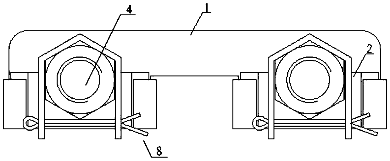
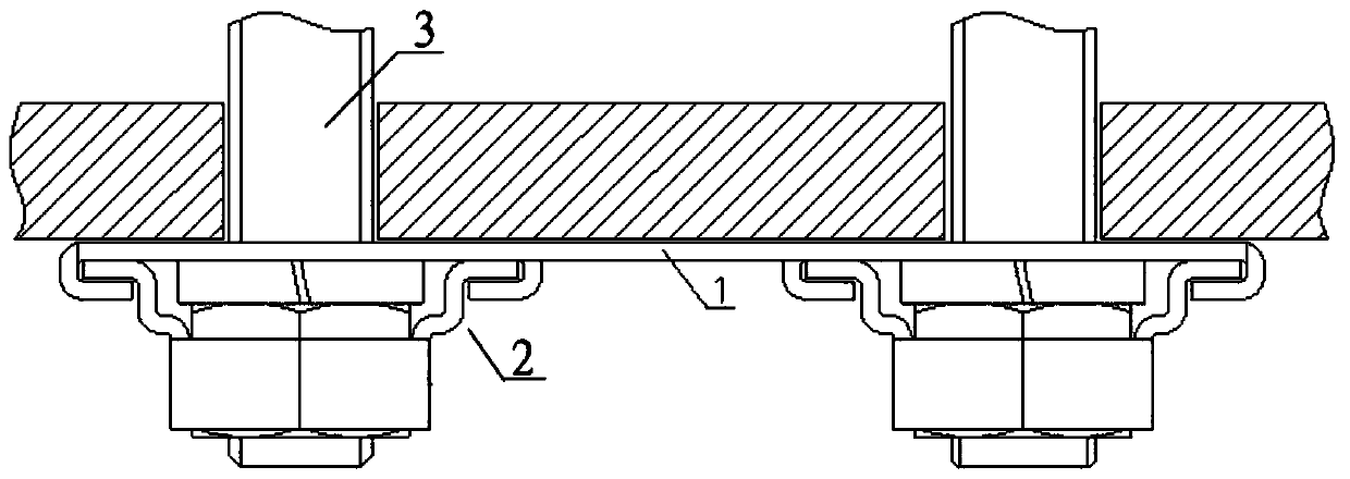
[0020] A mechanical anti-loosening structure for turnout fasteners, such as figure 1 , figure 2 As shown, it includes an anti-rotation support 1 and an anti-loosening piece 2. The anti-rotation support 1 is installed on the opposite rail waist of the turnout component parts, and its two sides are respectively connected with the rail waist of the rail member and the turnout by bolts 3 and nuts 4. Assembly parts fastened together.

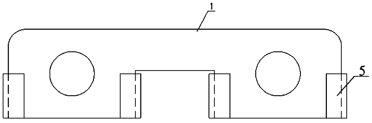
[0021] The anti-rotation support 1 is symmetrically provided with slots 5 on the side facing away from the rail waist, such as image 3 , Figure 4 shown. The anti-loosening piece 2 includes an engaging portion 6 that fits on the outer surface of the nut and has an open bottom, and an inserting portion 7 that cooperates with the slot, and the inserting portion 7 is fixed on the engaging portion 6, Such as Figure 5 , Figure 6 shown.

[0022] When installing the turnout assembly parts, first install the anti-rotation support 1 on the opposite...


PUM


Abstract

The invention provides a turnout fastener mechanical anti-loosening structure which comprises an anti-rotating support and anti-loosening pieces, the anti-rotating support is installed on the oppositeside rail web of a turnout assembly part, the two sides of the anti-rotating support are fastened to the rail web of a steel rail part and the turnout assembly part through bolts and nuts respectively, and inserting grooves are symmetrically formed in the side, back on to the rail web, of the anti-rotating support; each anti-loosening piece comprises a clamping part attached to the outer side face of the nut and provided with an opening in the bottom and an inserting part matched with the corresponding inserting groove, and each inserting part is fixed to the corresponding clamping part. In afastened state, the clamping parts are arranged above the nuts in a sleeving mode from top to bottom and attached to the nuts, meanwhile, the inserting parts are inserted into the inserting grooves,and the bottoms of the clamping parts are fixed through cotter pins. The anti-loosening structure is firm in anti-loosening effect, the anti-rotating support does not need to abut against the upper inclined face and the lower inclined face of the rail web space, the space needed for installation of the anti-loosening pieces is small, and therefore the anti-loosening structure can be universally suitable for different rail types and bolt hole center heights and is high in universality.

Description

technical field [0001] The invention relates to the technical field of railway turnouts, in particular to a mechanical anti-loosening structure of turnout fasteners with good versatility. Background technique [0002] Railway turnouts are laid on flexible foundations such as ballast and rubber cushions. Under the action of dynamic loads when trains pass by, the overall structure of the turnout will vibrate greatly, which may cause the fasteners of the turnout to loosen or even fall off, endangering traffic safety. For this problem, it is easy to think of starting from the following three aspects: 1. Fastening with double nuts; 2. Preventing loosening by setting spring washers; 3. Loosening by restricting the rotation of bolts and nuts. The mechanical anti-loosening method of restricting the rotation of bolts and nuts is the most reliable of the three schemes. [0003] Therefore, the anti-loosening structure of existing turnout fasteners generally adopts the form of rail g...

Claims


Application Information

Patent Timeline
Patent Type & Authority Applications(China)
IPC IPC(8): E01B9/58E01B9/64
CPCE01B9/58E01B9/64
Inventor 龙元柳亚楠崔琨喨周振马艳玲李鑫李德福
Owner CHINA RAILWAY SHANQIAO GRP CO LTD
Why Eureka
Try Eureka