
Dust removal device for mining equipment

A mining equipment and dust removal device technology, applied in mining equipment, combined devices, safety devices, etc., can solve the problems of polluting the surrounding environment, poor air dust removal effect, complex structure, etc., and achieve water saving, good dust removal effect, no dust removal The effect of dead ends

Inactive Publication Date: 2020-03-24
ZHUZHOU TIANQIAO SHUNCHEN COAL PREPARATION MACHINERY
View PDF5 Cites 7 Cited by
  • Summary
  • Abstract
  • Description
  • Claims
  • Application Information

AI Technical Summary

Problems solved by technology

[0003] A large amount of dust pollutants will be produced during the mining process. Improper treatment of these pollutants will not only affect the health of the operator, but also pollute the surrounding environment. However, the dust removal effect of some existing dust removal devices is not very ideal. , the dust removal effect on the air is poor, and the structure is complicated, which is not easy to use

Method used


Image

  • Dust removal device for mining equipment
  • Dust removal device for mining equipment
  • Dust removal device for mining equipment

Examples


Embodiment 1

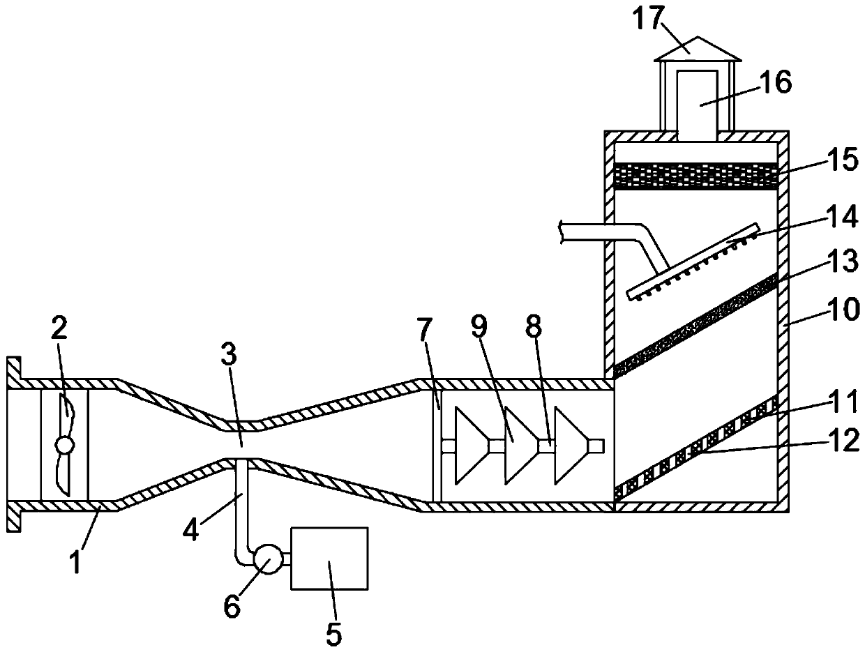
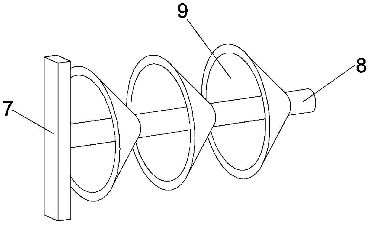
[0023] See Figure 1-2 , A dust removal device used in mining equipment includes a first pipe 1 and a second pipe 10. An air suction fan 2 is installed on the left side of the first pipe 1, and the middle of the first pipe 1 shrinks to form a throat 3, A water inlet pipe 4 is connected below the throat 3, and the lower end of the water inlet pipe 4 is connected to a water tank 5; a fixing plate 7 is vertically installed on the right side of the first pipe 1, and a connecting shaft 8 is provided on the fixing plate 7 , The connecting shaft 8 is evenly distributed with a number of tapered baffles 9; the right end of the first pipe 1 is in communication with the second pipe 10, and the second pipe 10 is sequentially installed with an inclined plate 11 and a filter from bottom to top. The plate 13 and the drying plate 15, the inclined plate 11 is provided with a number of through holes 12, the filter plate 13 and the drying plate 15 are provided with a spray head 14; the upper end ...

Embodiment 2

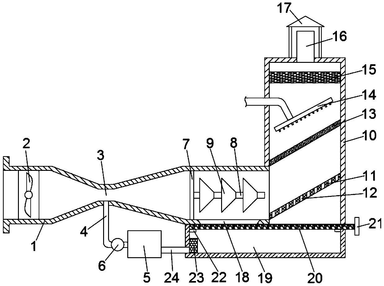
[0032] See image 3 When the dust-laden air carrying a large amount of water vapor collides with the conical baffle 9 and the inclined plate 11, some water droplets with large particles of dust will fall due to their heavy weight. In order to facilitate the collection of this part of the water droplets, this implementation The example is further improved on the basis of Example 1. The improvement is: a collection box 19 is provided below the tapered baffle 9 and the inclined plate 11, and the top of the collection box 19 is connected to the right end of the first pipe 1. Connected to the bottom of the second pipe 10, the right bottom of the first pipe 1 is provided with a through groove 18, and a filter 23 is installed on the inner wall of the collecting tank close to the water tank 5. The filter 23 and the water tank 5 There is a return pipe 24 connected between;

[0033] Specifically, water droplets containing large particles of dust fall from the first pipe 1 and the second pi...


PUM


Abstract

The invention discloses a dust removal device for mining equipment. The dust removal device comprises a first pipeline and a second pipeline, and the inner left side of the first pipeline is providedwith a suction fan; the pipe diameter of the middle part of the first pipeline is contracted to form a throat part, and the lower side of the throat part communicates with a water inlet pipe; the inner right side of the first pipeline is vertically provided with a fixing plate and a connecting shaft, and the connecting shaft is provided with a plurality of conical baffles uniformly; and the righttail end of the first pipeline communicates with the second pipeline, and the second pipeline is internally provided with an oblique plate, a filter plate and a drying plate from bottom to top in sequence. According to the dust removal device for the mining equipment, the throat part formed through pipe diameter shrinkage is arranged at the middle of the first pipeline, so water vapor is impacted;thus, dust and water drops in air are mixed, and primary dust removal is finished; the dust removal effect is good; the dust removal device is further provided with a collection box, and filtered water is reused; water resources are saved; the second pipeline is internally provided with the filter plate and the drying plate separately for secondary dust removal and water vapor absorption; and thedust removal is thorough, and no dead angle exists.

Description

Technical field [0001] The invention relates to the technical field of mining auxiliary equipment, in particular to a dust removal device used in mining equipment. Background technique [0002] Mine mining refers to the exploitation of valuable natural mineral resources manually or mechanically. According to the different buried depth of the deposit and the requirements of technical and economic rationality, mining is divided into open-pit mining and underground mining, close to the surface and buried Open-pit mining is used for the shallower part and underground mining for the deep part. [0003] A large amount of dust-like pollutants will be generated in the mining process. Improper handling of these pollutants will not only affect the health of the operator, but also pollute the surrounding environment. The dust removal effect of some existing dust removal devices is not very satisfactory. , The air dust removal effect is poor, and the structure is complex, not easy to use. Su...

Claims


Application Information

Patent Timeline
IPC IPC(8): E21F5/20E21F5/02B01D47/06B01D50/00B01D53/26
CPCE21F5/20E21F5/02B01D47/06B01D53/266B01D50/60
Inventor 凌英黄亚飞刘远力
Owner ZHUZHOU TIANQIAO SHUNCHEN COAL PREPARATION MACHINERY
Learn More