

Anti-misoperation locking logic expression graphical configuration method and system
A technology of logical expression and graphical configuration, applied in the direction of program control device, user interface execution, etc., can solve the problems of cumbersome operation and error-prone, and achieve the effect of simple operation, less error-prone and guaranteed consistency
- Summary
- Abstract
- Description
- Claims
- Application Information
AI Technical Summary
Problems solved by technology
Method used
Image

Examples
Embodiment 1
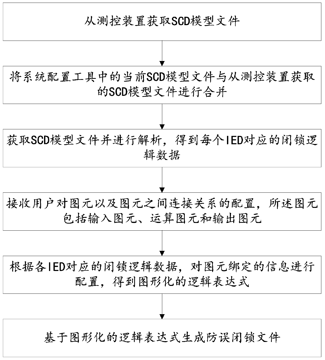
[0047] This embodiment discloses a graphical configuration method for anti-false locking logic expressions, such as figure 2 shown, including the following steps:
[0048] Step 1: Connect the measurement and control device through FTP, and call the current SCD model file of the measurement and control device;
[0049] Step 2: Merge the current SCD model file in the system configuration tool with the SCD file obtained from the measurement and control device;
[0050] Specifically, compare the two, obtain the data content that exists in the SCD model file of the measurement and control device but not in the system configuration tool, and incorporate it into the SCD model file of the system configuration tool.
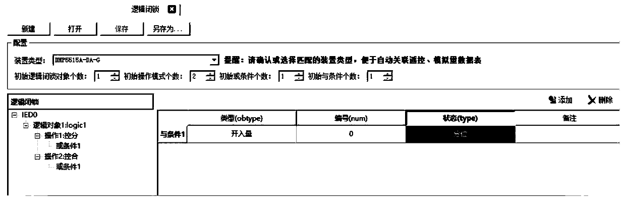
[0051] Step 3: Obtain the merged SCD model file, analyze the logical combination relationship corresponding to each IED in the SCD model file, such as internal signal, external signal, process signal and output signal, etc., to obtain the blocking logic data.
[0052] ...
Embodiment 2
[0070] The purpose of this embodiment is to provide a system for graphically configuring logic expressions for preventing false locking.
[0071] A graphical configuration system for preventing false locking logic expressions, including:
[0072] The SCD model file analysis module is used to obtain and analyze the SCD model file to obtain the corresponding locking logic data of each IED;
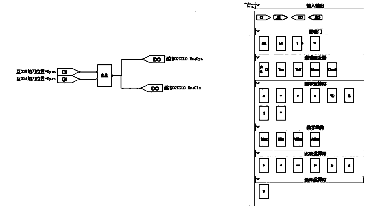
[0073] The graph element combination configuration module receives the user's configuration of the graph primitives and the connection relationship between the graph primitives, and the graph primitives include input graph primitives, operation graph primitives and output graph primitives.
[0074] The graphic element information binding module configures the information of graphic element binding according to the block logic data corresponding to each IED, and obtains a graphical logical expression;
[0075] The anti-mislocking file generation module generates anti-mislocking files based o...
Embodiment 3
[0077] The purpose of this embodiment is to provide a substation system configuration tool.
[0078] A substation system configuration tool configured to be able to generate an anti-incorrect locking file based on the graphical configuration method of the anti-incorrect locking logic expression in the first embodiment above.
PUM
 Abstract
Description
Claims
Application Information