
Display driving method and liquid crystal display device

A liquid crystal display device and display driving technology, which can be applied to static indicators, instruments, etc., and can solve problems such as large viewing angle deviation, reduced sub-pixel charging time, and low cost.

Inactive Publication Date: 2020-03-24
TCL CHINA STAR OPTOELECTRONICS TECH CO LTD
View PDF8 Cites 10 Cited by
  • Summary
  • Abstract
  • Description
  • Claims
  • Application Information

AI Technical Summary

Problems solved by technology

[0004] With the development of display technology, the resolution and refresh rate of LCD panels are getting higher and higher. The LCD panel with a resolution of 8K and a refresh rate of 120Hz will be the mainstream in the future. For a resolution of 8K, a refresh rate of 120Hz For liquid crystal display panels, the number of pixels is greatly increased, but the refresh time of each frame is greatly reduced, which means that the charging time of each row of sub-pixels is greatly reduced. If a conventional row of sub-pixels and one scanning line are used, With a pixel structure of one column of sub-pixels and one data line, the charging time of each sub-pixel cannot be guaranteed, resulting in insufficient charging and abnormal picture. At the same time, considering the product cost, the 4-domain pixel structure has a lower cost than the 8-domain pixel structure. At the same time, the 4-domain pixel structure has a serious problem of large viewing angle

Method used


Image

  • Display driving method and liquid crystal display device
  • Display driving method and liquid crystal display device
  • Display driving method and liquid crystal display device

Examples


Embodiment Construction

[0038] In order to further illustrate the technical means adopted by the present invention and its effects, the following describes in detail in conjunction with preferred embodiments of the present invention and accompanying drawings.

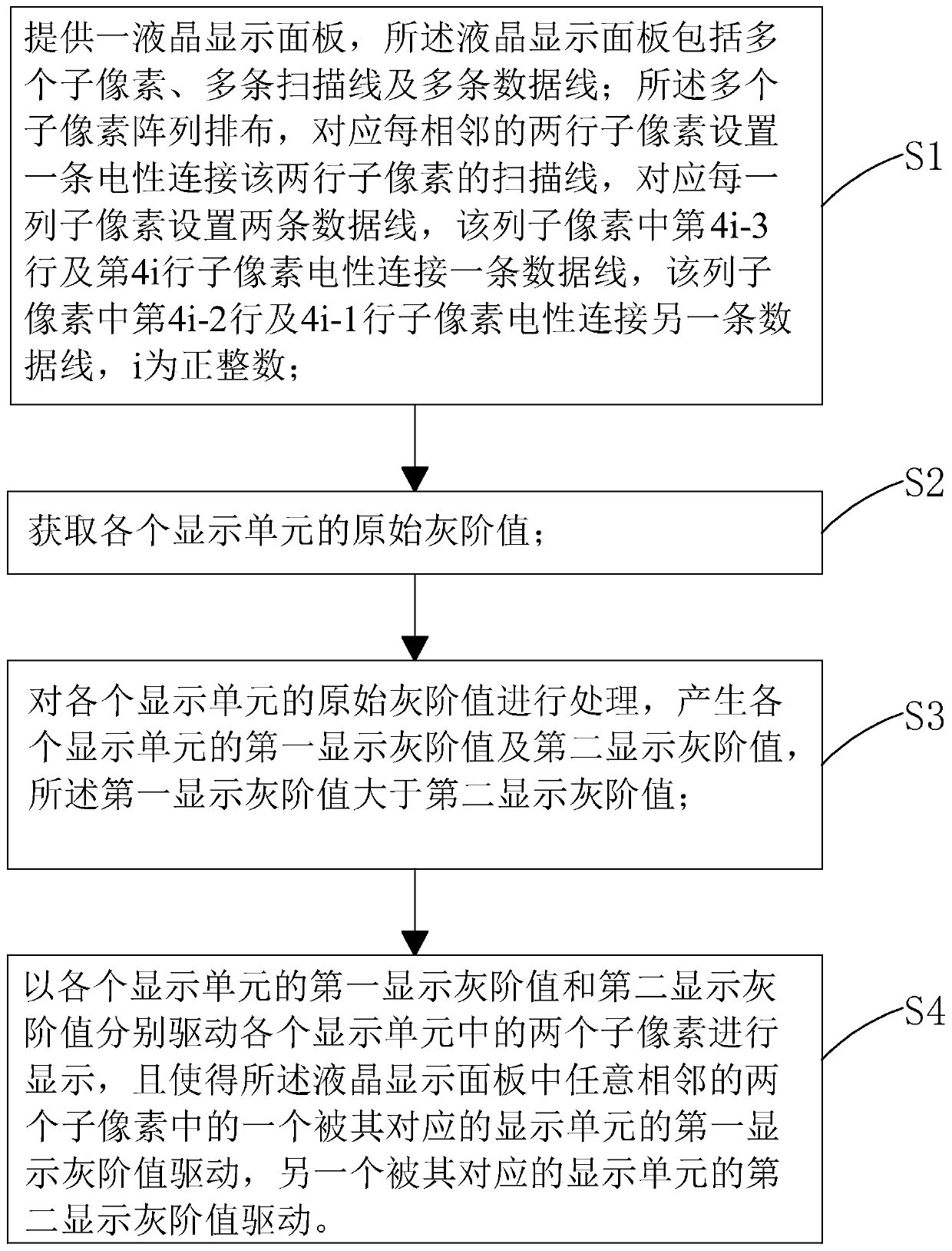
[0039] see image 3 , the present invention provides a display driving method, comprising the following steps:

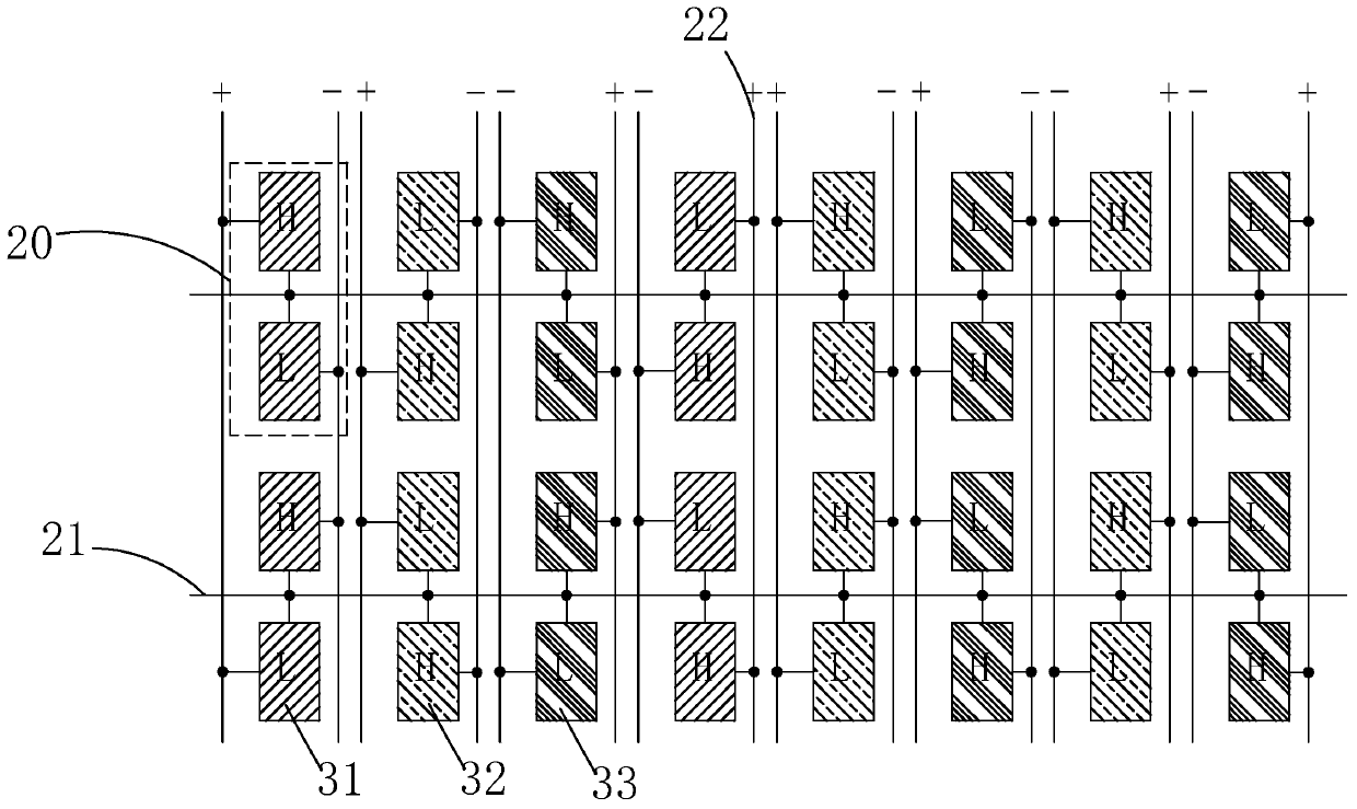
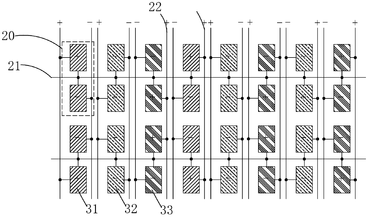
[0040] Step S1, providing a liquid crystal display panel 10, the liquid crystal display panel 10 includes a plurality of sub-pixels, a plurality of scanning lines 21 and a plurality of data lines 22;

[0041]The plurality of sub-pixels are arranged in an array, corresponding to every two adjacent rows of sub-pixels, a scanning line 21 electrically connected to the two rows of sub-pixels is provided, and two data lines 22 are provided corresponding to each column of sub-pixels. The sub-pixels in row 4i-3 and row 4i are electrically connected to one data line 22, and the sub-pixels in row 4i-2 and row 4i-1 in this column are electric...


PUM


Abstract

The invention provides a display driving method and a liquid crystal display device. The display driving method comprises the following steps of providing a liquid crystal display panel of an HG2D framework, and setting every two adjacent sub-pixels in the same column of sub-pixels in the liquid crystal display panel to be one display unit; obtaining an original gray-scale value of each display unit; processing the original gray-scale value of each display unit to generate a first display gray-scale value and a second display gray-scale value of each display unit; using the first display gray-scale value and the second display gray-scale value of each display unit for respectively driving two sub-pixels in each display unit to display; driving one of any two adjacent sub-pixels in the liquid crystal display panel by the first display gray-scale value of the display unit corresponding to the sub-pixel. According to the invention, the HG2D architecture is matched with the brightness change processing, so that the charging time of the sub-pixels can be ensured, the large-view-angle color cast can be improved, and the display effect can be improved.

Description

technical field [0001] The invention relates to the field of display technology, in particular to a display driving method and a liquid crystal display device. Background technique [0002] A Liquid Crystal Display (LCD) has many advantages such as a thin body, power saving, and no radiation, and has been widely used. Such as: LCD TV, mobile phone, personal digital assistant (PDA), digital camera, computer screen or notebook computer screen, etc., occupy a dominant position in the field of flat panel display. [0003] Due to the optical anisotropy of liquid crystal molecules, existing liquid crystal display panels have the problem of narrow viewing angles of chromaticity, which affects people's viewing experience at large viewing angles. In order to improve the chromaticity and narrow viewing angle of the liquid crystal display panel, the prior art proposes a multi-domain pixel structure. The multi-domain pixel structure is to subdivide each sub-pixel into a plurality of sm...

Claims


Application Information

Patent Timeline
Patent Type & Authority Applications(China)
IPC IPC(8): G09G3/36
CPCG09G3/3607G09G2320/0271
Inventor 王耿
Owner TCL CHINA STAR OPTOELECTRONICS TECH CO LTD
Learn More