Cabinet door supporting device for electric appliance panel cabinet

A technology for supporting devices and cabinet doors, applied in the substation/distribution device housing, substation/switch layout details, electrical components, etc. Effect

Inactive Publication Date: 2020-03-24
西安鼎腾电子科技有限公司
View PDF3 Cites 3 Cited by
  • Summary
  • Abstract
  • Description
  • Claims
  • Application Information

AI Technical Summary

Problems solved by technology

[0004] The object of the present invention is to provide a cabinet door support device for electrical panel cabinets, so as to solve the problem that the cabinet doors in the prior art proposed in the above background technology have insufficient flexibility. Under such circumstances, it is necessary to carry out emergency repairs in time. Due to the strong wind and other uncertainties, the cabinet doors are opened and closed without control, which has certain potential safety hazards.

Method used


Image

  • Cabinet door supporting device for electric appliance panel cabinet
  • Cabinet door supporting device for electric appliance panel cabinet
  • Cabinet door supporting device for electric appliance panel cabinet

Examples


Embodiment 1

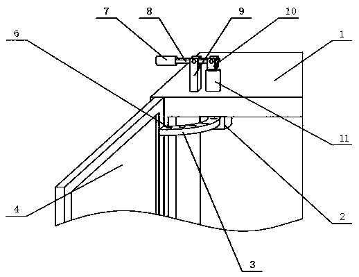
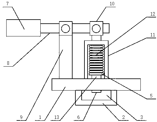
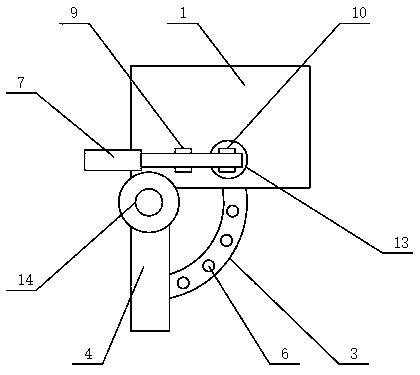
[0018] see Figure 1-3 , the present invention provides a technical scheme of a cabinet door support device for an electrical panel cabinet: it includes a cabinet body 1, the front of the cabinet body 1 is hinged with a cabinet door 4 through a hinge 14, and the inner wall of the cabinet door 4 is fixedly connected with an arc-shaped sliding plate 3 , the top of the curved slide 3 is provided with a plurality of card holes 6, the inside of the cabinet 1 is fixedly connected with the bracket 2, one end of the curved slide 3 is slidably connected with the bracket 2, and the top of the cabinet 1 is fixedly connected with the sleeve 11. The inside of the sleeve 11 is slidingly connected with a sliding rod 13, the bottom end of the sliding rod 13 runs through the cabinet body 1 and extends to the inside of the bracket 2, the sliding rod 13 is fixedly connected with the clamping plate 5, and the clamping plate 5 and the sleeve 11 Between them are elastically connected by spring 12. ...

Embodiment 2

[0020] On the basis of embodiment one, refer to figure 2 combine image 3 , the bottom of the slide bar 13 is adapted to the card hole 6, the top of the slide bar 13 runs through the top of the sleeve 11 and extends to the outside, the top of the slide bar 13 is fixedly connected with the lever 8, and the top of the cabinet 1 is fixedly connected with a The support rod 9 is located on one side of the sleeve 11, the top of the support rod 9 is rotatably connected with a lever 8, one end of the lever 8 is rotatably connected with the rotating head 10, and the other end of the lever 8 is fixedly connected with the handle 7, the handle 7 The outer surface of the outer surface is covered with a rubber sleeve. When the cabinet door 4 is opened, the handle 7 is pressed down earlier. At this time, the other end of the lever 8 drives the slide bar 13 to move upward through the rotating head 10. At this time, the slide bar 13 The bottom end of the bottom end no longer blocks the clamp...


PUM


Abstract

The invention discloses a cabinet door supporting device for an electric appliance panel cabinet, and the device comprises a cabinet body, the front surface of the cabinet body is hinged with a cabinet door through a hinge, the inner wall of the cabinet door is fixedly connected with an arc-shaped sliding plate, and the top end of the arc-shaped sliding plate is provided with a plurality of clamping holes. When the device is used, when the cabinet door is opened, at the moment, the handle is pressed downwards, the other end of the lever drives the sliding rod to move upwards through the rotating head. When the opening and closing angle for opening and closing the cabinet door is determined, the handle is loosened, at the moment, the spring drives the sliding rod to move downwards through the clamping plate, so the the sliding rod is clamped with the clamping hole in the top end of the arc-shaped sliding plate, so that the cabinet door is fixed. Compared with an existing electric appliance panel cabinet, the cabinet door can be limited when the cabinet door is opened and closed, so that the cabinet door is prevented from being automatically closed under the influence of wind power during overhauling, the personal safety of overhauling personnel is protected, and potential safety hazards are eliminated.

Description

technical field [0001] The invention relates to an electrical panel cabinet, in particular to a cabinet door support device for the electrical panel cabinet. Background technique [0002] The electrical panel cabinet is a power distribution and control unit for the integration of electrical components, control components and corresponding housings in the electrical power distribution and control system. In the electrical system, power transmission, distribution, equipment drive and control are all It is inseparable from electrical panel cabinets, and electrical panel cabinets are often seen in power distribution of public buildings and residential quarters in daily life. [0003] In view of this, Chinese Patent No. CN209627895U proposes a waterproof electrical cabinet with automatic door panel reset; Chinese Patent No. CN209609039U proposes an electrical cabinet that is easy to disassemble; Chinese Patent No. CN209608181U proposes an outdoor electrical cabinet. However, the...

Claims


Application Information

Patent Timeline
IPC IPC(8): H02B1/38H02B1/30
CPCH02B1/306H02B1/38
Inventor 何飞
Owner 西安鼎腾电子科技有限公司
Why Eureka
Try Eureka