A forward and flyback switching power supply circuit

A switching power supply circuit, flyback technology, applied in the direction of high-efficiency power electronic conversion, electrical components, regulating electrical variables, etc., can solve problems such as low output voltage and increased loss, achieve simple control logic, solve fatal defects, and improve performance. and the effect of reliability

Active Publication Date: 2020-12-18
MORNSUN GUANGZHOU SCI & TECH
View PDF6 Cites 0 Cited by
  • Summary
  • Abstract
  • Description
  • Claims
  • Application Information

AI Technical Summary

Problems solved by technology

[0010] In view of this, the technical problem to be solved by the present invention is to propose a forward and flyback switching power supply circuit, which is applied to the step-up occasion where the output voltage is much higher than the input voltage. The topology control of the transformer is relatively simple, and the output voltage is completely solved. The problem of sharp increase in loss caused by low or short circuit makes this topology easier to productize

Method used


Image

  • A forward and flyback switching power supply circuit
  • A forward and flyback switching power supply circuit
  • A forward and flyback switching power supply circuit

Examples


no. 1 example

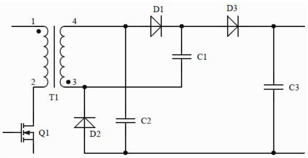
[0038] figure 2 It shows the principle diagram of the first embodiment of the forward and flyback switching power supply circuit of the present invention, including the primary side circuit, the transformer T1 and the secondary side circuit, the primary side circuit includes the switching tube Q1, and the drain of the switching tube Q1 is connected to the original circuit of the transformer T1 The two ends of the side winding, the source of the switch tube Q1 are grounded; the secondary side circuit specifically includes diode D1, diode D2, diode D3, capacitor C1, capacitor C2, capacitor C3, switch tube Q2, diode D4, and diode D4 is the switch tube Q2 The body diode of the transformer T1; terminal 1 of the primary winding of the transformer T1 and terminal 3 of the secondary winding of the transformer T1 have the same name, and terminal 4 of the secondary winding of the transformer T1 is connected to the drain of the switching tube Q2 and the anode of the diode D1. The source...

no. 2 example

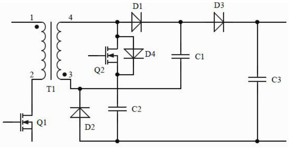
[0042] The second example is image 3 As shown, the difference from the first embodiment is that the switching tube Q2 of the second embodiment uses an N-MOS tube and the series position is changed between the diode D1 and the capacitor C1, and the drain of the switching tube is connected to the cathode of the diode D1 , the source of the switch tube is connected to one end of the capacitor C1.

[0043] The working principle of this embodiment is the same as that of the first embodiment, and will not be repeated here.

no. 3 example

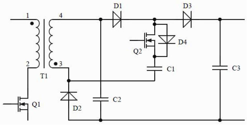
[0045] The third embodiment is for example Figure 4 As shown, the difference from the first embodiment is that the switching tube Q2 of the third embodiment uses a P-MOS tube and the position in series is changed between the diode D2 and the capacitor C2, and the drain of the switching tube is connected to the other side of the capacitor C2. At one end, the source of the switch tube is connected to the anode of the diode D2.

[0046] The working principle of this embodiment is the same as that of the first embodiment, and will not be repeated here.


PUM


Abstract

The invention discloses a forward and flyback switching power supply circuit, which is applied to the boosting occasion where the output voltage is much higher than the input voltage, and the output voltage can be adjusted. The controllable switch device in the present invention is used as a control switch. When the output is short-circuited or the output voltage is low, the controllable switch device is controlled to be disconnected, so that the entire circuit works in a flyback state, which greatly reduces short-circuit power consumption and output Efficiency: When the output voltage is high, the switch tube is controlled to be turned on, so that the whole circuit works in a forward and flyback state, which reduces the voltage stress of the power tube of the whole circuit, which is conducive to device selection and further improves the efficiency of the whole machine.

Description

technical field [0001] The invention relates to the field of switching power supplies, in particular to a forward and flyback switching power supply circuit. Background technique [0002] Nowadays, high-voltage constant-current charging converters are used in many fields. Generally, the basic topology of flyback is used in the field of high-voltage and low-power output. The voltage is increased by multi-winding or multi-stage voltage doubler rectification by capacitors and diodes. The purpose of high output voltage, but the above methods have certain limitations: [0003] The method of multi-winding rectification and then serial output is equivalent to multiple flyback outputs in series. The higher the output voltage, the more windings are required. It is a challenge for the volume of the transformer. In addition, the distance between the pins of the transformer needs to be further increased. Large, so the size of the entire transformer will be larger; [0004] The method ...

Claims


Application Information

Patent Timeline
Patent Type & Authority Patents(China)
IPC IPC(8): H02M3/335H02M1/32H02M1/36
CPCH02M1/32H02M1/36H02M3/33576H02M1/0048H02M1/0054Y02B70/10
Inventor 许梦羊张彦斌冯刚
Owner MORNSUN GUANGZHOU SCI & TECH
Why Eureka
Try Eureka