Clinical emergency breathing device for internal medicine

A breathing device and clinical technology, applied in the medical field, can solve problems such as the inability to achieve rapid breathing of patients, the inability to achieve rapid reset of the pressure plate, and dangers caused by untimely treatment, and achieve the effect of simple structure, low production cost and good effect

Inactive Publication Date: 2020-03-27
陈彦群
View PDF0 Cites 0 Cited by
  • Summary
  • Abstract
  • Description
  • Claims
  • Application Information

AI Technical Summary

Problems solved by technology

[0002] Internal medicine is a specialty of clinical medicine, which is the foundation of almost all other clinical medicines. Symptoms, symptoms, experimental diagnosis, imaging examination, differential diagnosis, diagnosis, treatment, prognosis, the method of internal medicine is to conduct physical examination after medical history inquiry or interview. Exclude those with low possibility in many differential diagnoses to obtain the most probable diagnosis; after obtaining the diagnosis, medical treatment methods include follow-up observation, lifestyle, drugs, interventional therapy, etc., and adjust the use of drugs according to the patient's condition. To prevent and deal with side effects and complications, emergency breathing devices are needed in clinical medicine, but the existing emergency breathing devices for internal medicine still have the following problems: 1. When a patient develops a disease, it cannot be automatically rescued, and medical personnel are required The treatment can only be carried out when the patient arrives, which leads to danger if the treatment is not timely; 2. The rapid reset of the pressure plate cannot be realized, so that the patient cannot breathe quickly, and the treatment effect is poor

Method used


Image

  • Clinical emergency breathing device for internal medicine
  • Clinical emergency breathing device for internal medicine
  • Clinical emergency breathing device for internal medicine

Examples


Embodiment Construction

[0018] The following will clearly and completely describe the technical solutions in the embodiments of the present invention with reference to the accompanying drawings in the embodiments of the present invention. Obviously, the described embodiments are only some, not all, embodiments of the present invention.

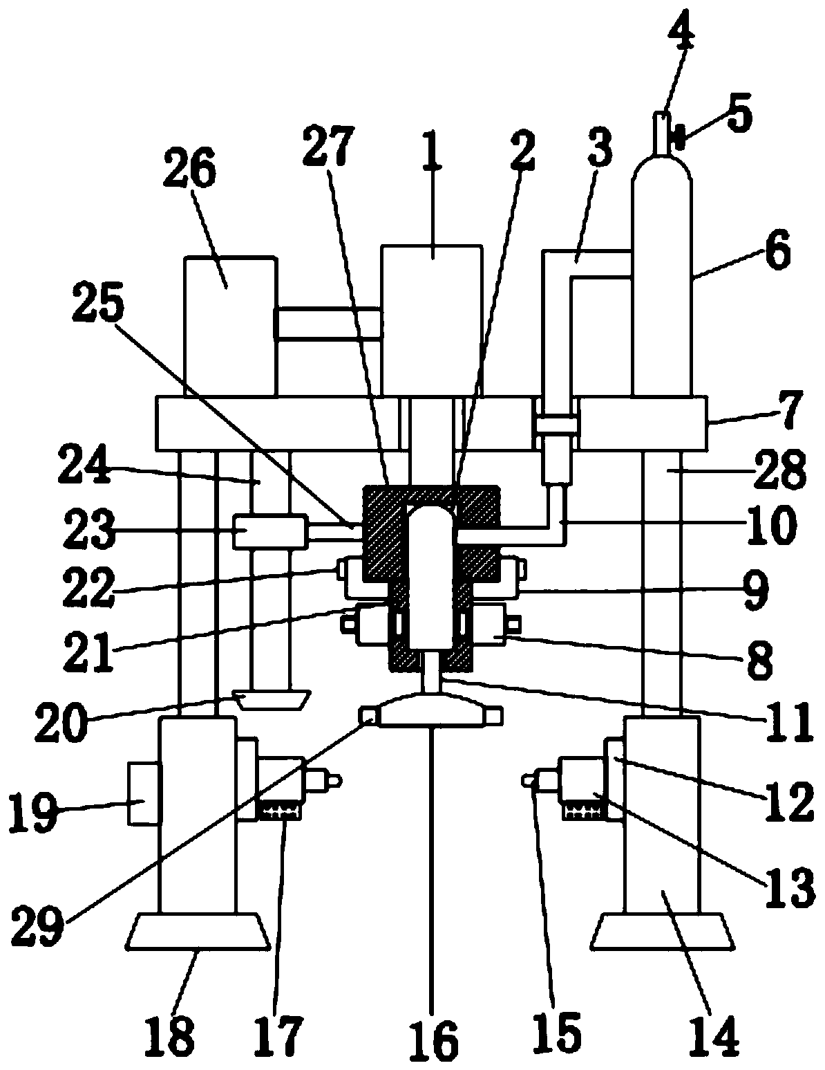
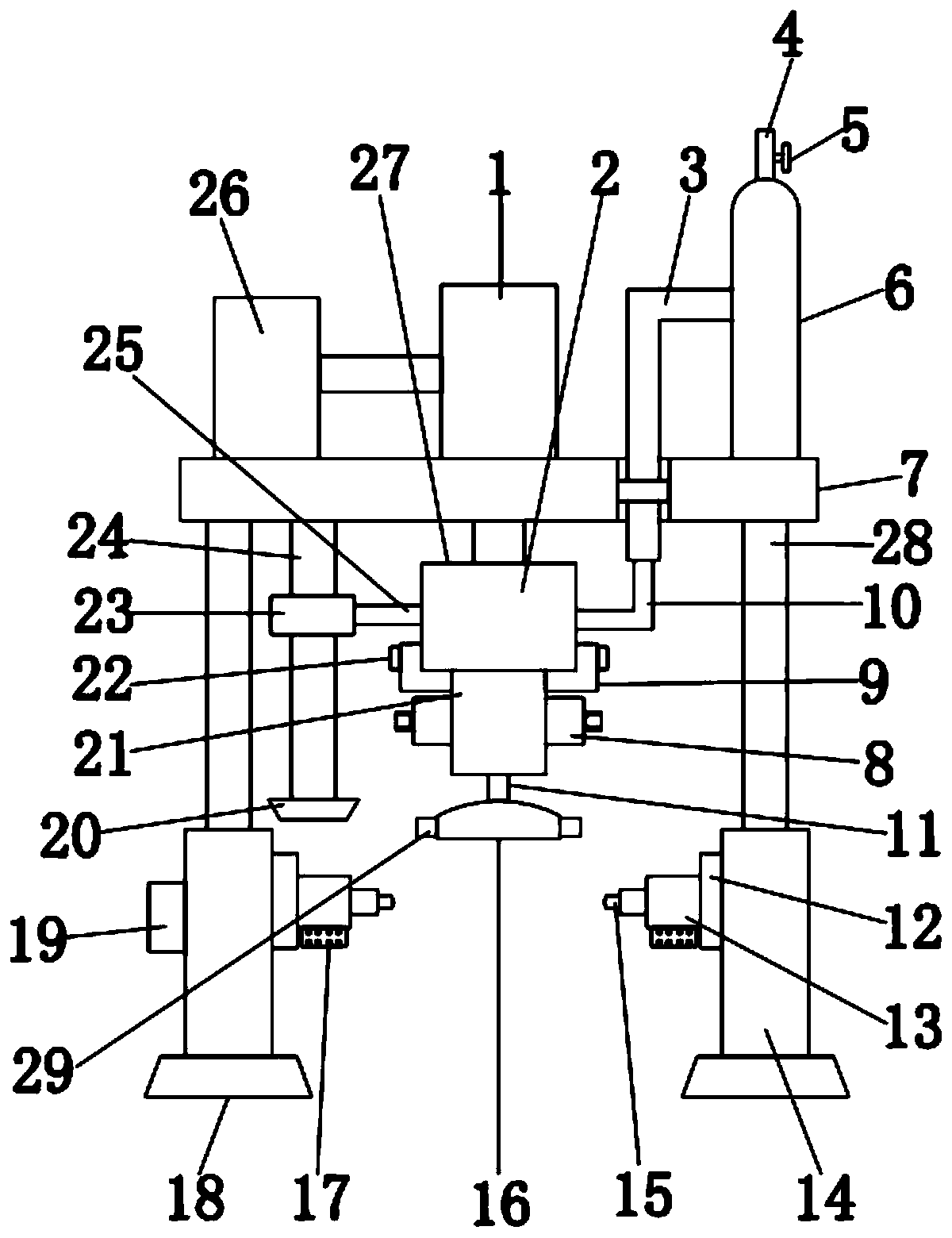
[0019] refer to Figure 1-3 , an emergency respiratory device for internal medicine clinical use, including a top plate 7, a controller 26 is installed on the top left side of the top plate 7, and the controller 26 can control the first electric telescopic rod 1 and the second electric telescopic rod 13 to work , the top center position of the top plate 7 is equipped with a first electric telescopic rod 1, and the bottom end of the first electric telescopic rod 1 is welded with a placement seat 27, and the placement seat 27 is a rectangular seat, and the placement seat 27 There is a groove inside, the left side of the placement seat 27 is welded with a crossbar 25, t...


PUM


Abstract

The invention discloses a clinical emergency breathing device for internal medicine. The emergency breathing device comprises a top plate, a controller is installed on the left side of the top end ofthe top plate, a first electric telescopic rod is installed in the center of the top end of the top plate, a placement seat is welded to the bottom end of the first electric telescopic rod, and a rubber bag is placed in the placement seat; a sealing cover is placed at the bottom end of the placement seat, extrusion reset devices are welded to the left side and the right side of the sealing cover,the bottom end of the supporting rod is sleeved with a sleeve, a fixing bolt is installed on the outer side of the sleeve, a base is welded to the bottom end of the sleeve, and a connecting seat is welded to the inner side of the sleeve; a second electric telescopic rod is welded to the inner side of the connecting base, an inserting rod is welded to the inner side of the second electric telescopic rod, and a frequency converter is installed at the bottom end of the second electric telescopic rod. According to the invention, automatic treatment can be carried out on a patient without the needfor medical staff to arrive for treatment, so that the patient can be treated in time.

Description

technical field [0001] The invention relates to the field of medical technology, in particular to an emergency respiratory device for clinical use in internal medicine. Background technique [0002] Internal medicine is a specialty of clinical medicine, which is the foundation of almost all other clinical medicines. Symptoms, symptoms, experimental diagnosis, imaging examination, differential diagnosis, diagnosis, treatment, prognosis, the method of internal medicine is to conduct physical examination after medical history inquiry or interview. Exclude those with low possibility in many differential diagnoses to obtain the most probable diagnosis; after obtaining the diagnosis, medical treatment methods include follow-up observation, lifestyle, drugs, interventional therapy, etc., and adjust the use of drugs according to the patient's condition. To prevent and deal with side effects and complications, emergency breathing devices are needed in clinical medicine, but the exis...

Claims


Application Information

Patent Timeline
Patent Type & Authority Applications(China)
IPC IPC(8): A61M16/00
CPCA61M16/0003A61M16/022A61M2202/0208A61M2230/40A61M2202/0007A61M2230/005
Inventor 陈彦群
Owner 陈彦群
Why Eureka
Try Eureka