Machine bottom surface spraying equipment

A bottom surface and spraying equipment technology, applied in spray booths, spraying devices, liquid spraying devices, etc., can solve problems such as difficult spraying on the bottom surface of the machine, and achieve good adaptability, larger spraying area, and uniform spraying effect

Active Publication Date: 2020-03-27
西安通用开关电气有限公司
6 Cites 4 Cited by

AI-Extracted Technical Summary

Problems solved by technology

[0003] The technical problem to be solved by the present invention is to provide a machine bottom sur...

Abstract

The invention discloses machine bottom surface spraying equipment. The machine bottom surface spraying equipment comprises a spraying box, wherein a working cavity is arranged in the spraying box, anda width judging mechanism is arranged in the working cavity; and the width judging mechanism comprises two supporting sleeves, wherein the supporting sleeves are fixedly arranged on the left side andthe right side of the rear end wall of the working cavity, a second telescopic sleeve is slidably arranged in each supporting sleeve, a first telescopic sleeve is slidably arranged in each second telescopic sleeve, and an extension rod is slidably arranged in each first telescopic sleeve. The spraying equipment can automatically spray the bottom surface of a machine after being placed at the bottom of the machine, and can automatically adjust the spraying power and the spraying angle according to the different widths of the bottom surface of the machine, the spraying is uniform, the adaptability is good, the spraying area is enlarged by arranging three spray heads, and the situation of incomplete spraying is effectively avoided.

Application Domain

Technology Topic

Image

  • Machine bottom surface spraying equipment
  • Machine bottom surface spraying equipment
  • Machine bottom surface spraying equipment

Examples

  • Experimental program(1)

Example Embodiment

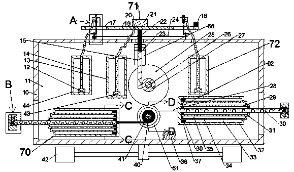
[0021] Combine below Figure 1-6 The present invention will be described in detail, in which, for the convenience of description, the following directions are specified as follows: figure 1 The vertical, horizontal, front and rear directions of the projection relationship are the same.
[0022] A spraying device for the bottom surface of a machine described in conjunction with Figures 1-6 includes a spraying box 10 in which a working chamber 11 is provided, and a width determining mechanism 70 is provided in the working chamber 11, and the width The judging mechanism 70 includes two support sleeves 32 fixedly arranged on the left and right sides of the rear end wall of the working chamber 11, a second telescopic sleeve 34 is slidably provided in the support sleeve 32, and a second telescopic sleeve 34 is slidably provided in the second telescopic sleeve 34. There is a first telescopic sleeve 31. An extension rod 30 is slidably provided in the first telescopic sleeve 31. One end of the extension rod 30 away from the support sleeve 32 is located in the external space, and the extension rod 30 in the external space is A clamping rod 55 is provided, the long end of the clamping rod 55 is located at the rear side of the extension rod 30, the short end of the clamping rod 55 is located at the front side of the extension rod 30, and the two support sleeves 32 There is a drive gear 61 between them. When the two extension rods 30 move away from each other, the drive gear 61 can rotate, placing the invention on the bottom of the machine, and manually pulling the clamping rod 55 can drive the extension rod 30 Away from the support sleeve 32, when the two clamping rods 55 move to the lower side of the left and right end walls of the machine, rotate the clamping rod 55 forward by ninety degrees, and the machine can be clamped by the two clamping rods 55 Left and right sides
[0023] An intermediate spraying mechanism 71 is provided on the upper side of the width judging mechanism 70. The intermediate spraying mechanism 71 includes a transmission gear 25 arranged on the upper side of the drive gear 61. The transmission gear 25 meshes with the drive gear 61. The front side of the gear 25 is provided with an output gear 27 coaxial with the transmission gear 25, the left side of the output gear 27 is meshed with a rack 15, and the spraying box 10 is provided with a top plate 19 on the upper side. As the rack 15 moves up and down, a first spray head 21 is installed on the upper end surface of the top plate 19, and the first spray head 21 is used for spraying at the middle position of the bottom of the machine;
[0024] Two side spraying mechanisms 72 are provided symmetrically in the working cavity 11, the side spraying mechanism 72 on the left side is used for spraying at the left side of the bottom of the machine, and the side spraying mechanism 72 on the right side is used for the bottom of the machine. Spray on the right position.
[0025] Advantageously, the width judging mechanism 70 further includes a torsion shaft 40 rotatably connected to the rear wall of the working chamber 11, and a first torsion spring 63 is provided between the torsion shaft 40 and the rear wall of the working chamber 11. The driving gear 61 is fixedly arranged on the torsion shaft 40, the front side of the driving gear 61 is provided with two winding wheels 41 fixedly connected to the torsion shaft 40, and the winding wheel 41 is wound up on the front side. A wire 62 fixedly connected with the extension rod 30 on the left side is wound, and the power device 42 on the rear side is wound with the wire 62 fixedly connected with the extension rod 30 on the right side. The cavity 33 is provided with a first receiving cavity 33 with an opening away from the driving gear 61, and a first sliding block 37 slidably connected to the first receiving cavity 33 is fixed on the second telescopic sleeve 34. The second telescopic sleeve 34 is provided with a second receiving cavity 35 with an opening away from the driving gear 61, and the first telescopic sleeve 31 is fixedly provided with a second sliding block 36 slidably connected with the second receiving cavity 35, so The first telescopic sleeve 31 is provided with a third receiving cavity 29 with an opening away from the driving gear 61, and a third sliding block 28 slidably connected to the third receiving cavity 29 is fixed on the extension rod 30, so The clamping rod 55 is provided with a cylindrical groove 56 that opens toward the spraying box 10, and the extension rod 30 is rotatably connected with the end wall of the cylindrical groove 56 away from the spraying box 10, and the cylindrical groove The end wall of 56 is provided with a first blocking groove 60 and a second blocking groove 64 that open toward the cylindrical groove 56, and the upper end surface of the extension rod 30 in the cylindrical groove 56 is provided with a spring with an opening facing upward. The lower end wall of the spring groove 57 is fixedly provided with a spring 58, and the upper end of the spring 58 is fixedly provided with a spring block 59 whose upper end is located in the first blocking groove 60.
[0026] Advantageously, the intermediate spraying mechanism 71 further includes a transmission shaft 26 rotatably connected with the rear wall of the working chamber 11, the output gear 27 and the transmission gear 25 are fixedly arranged on the transmission shaft 26, The rear end wall of the working chamber 11 is provided with a moving groove 66 with an opening facing forward. A moving block 23 is slidably provided in the moving groove 66. The front end of the moving block 23 is located in the working chamber 11 and a moving rod 22 is fixed. The rack 15 is fixedly arranged at the lower end of the moving rod 22, the upper end of the moving rod 22 is located in the external space, the top plate 19 is fixedly connected with the upper end surface of the moving rod 22, and the left side of the transmission gear 25 A storage box 13 fixedly connected to the rear wall of the working chamber 11 is provided, and a first pump 43 is provided in the storage box 13, and the first pump 43 is connected to the first spray head 21 through a first hose 20.
[0027] Advantageously, the side spraying mechanism 72 includes a storage box 44 fixedly connected to the rear end wall of the working chamber 11, the storage box 44 is provided with a second pump 12, and the upper end surface of the top plate 19 is fixedly provided with The support plate 52, the top plate 19 is provided with a connecting cavity 17 penetrating the upper and lower end surfaces of the top plate 19, the front end of the support plate 52 is fixedly provided with a support rod 53, and the support rod 53 passes through a second torsion spring 51 is rotated with a support block 50, the upper end of the support block 50 is mounted with a second spray head 49, the lower end of the support block 50 is fixed with a rotating plate 54 penetrating the connecting cavity 17, the second spray head 49 and The second pump 12 is connected by a second hose 14.
[0028] Advantageously, a distance sensor 16 is fixed on the right side of the upper end surface of the top plate 19, and two power shafts 47 are symmetrically provided on the upper end surface of the spraying box 10, and a pulley 46 and a cam are fixed on the power shaft 47. 48. The two pulleys 46 are frictionally driven by the belt 24, and a power motor 45 for controlling the power shaft 47 is provided on the lower side of the left power shaft 47, and the power motor 45 is fixed to the upper end surface of the spraying box 10 Connected, the power shaft 47 on the right side is rotatably connected with the upper end surface of the spraying box 10.
[0029] Beneficially, a controller 38 is fixed on the lower end wall of the working chamber 11, a power device 42 is installed on the lower end surface of the spraying box 10, and the controller 38 is used to control the power device 42.
[0030] The sequence of mechanical actions of the entire invention:
[0031] In the initial state: the first torsion spring 63 and the spring 58 are in a normal state
[0032] Manually place the present invention on the bottom of the machine, manually pull the two clamping rods 55, so that the left clamping rod 55 moves to the left of the left end of the machine, and the right clamping rod 55 moves to the right of the right end of the machine, and then manually forward Rotate the two clamping rods 55, clamp the machine by the two clamping rods 55, the clamping rod 55 drives the extension rod 30 to move, the extension rod 30 pulls the wire 62, drives the reel 41 to rotate, and the reel 41 drives the torque The shaft 40 rotates, the first torsion spring 63 is compressed, and the torsion shaft 40 drives the drive gear 61 to rotate. According to the distance between the left and right end faces of the machine, the extension rod 30, the first telescopic sleeve 31 and the second telescopic sleeve 34 are all changed to different degrees. Pull out, the extension rod 30 is pulled out first, then the first telescopic sleeve 31, and then the second telescopic sleeve 34;
[0033] Through the meshing of the drive gear 61 and the drive gear 25, the drive gear 25 is driven to rotate, the drive gear 25 drives the drive shaft 26 to rotate, and the drive shaft 26 drives the output gear 27 to rotate. The output gear 27 meshes with the rack 15 to drive the rack 15 When descending, the rack 15 drives the moving rod 22 to descend, thereby driving the top plate 19 to descend. The distance sensor 16, the first nozzle 21 and the second nozzle 49 descend with the top plate 19, and the width between the left and right ends of the machine, that is, the width of the bottom of the machine is wider When the distance between the top plate 19 and the bottom of the machine increases, the distance sensor 16 is used to detect the distance from the bottom of the machine. When the distance sensor 16 detects an increase in the distance from the bottom of the machine, the second pump 12 and the first pump 43 will increase at the same time. Power used;
[0034] Start the second pump 12, the first pump 43 and the power motor 45. The first pump 43 sprays the paint in the storage tank 13 to the middle position of the bottom of the machine through the first nozzle 21. The power motor 45 drives the power shaft 47 to rotate, and the power shaft 47 The pulley 46 and the cam 48 are driven to rotate. Through the friction transmission of the belt 24, the left pulley 46 drives the right pulley 46 to rotate, thereby driving the right cam 48 to rotate at the same time, and the cam 48 pushes the rotating plate 54 to rotate, driving the second nozzle 49 rotates, under the reset action of the second torsion spring 51, the second spray head 49 can be driven to swing left and right. The second pump 12 sprays the paint in the storage box 44 through the second spray head 49, and cooperates with the second spray head 49 which swings left and right. Spray paint on the left and right sides of the bottom of the machine. When the width of the bottom of the machine becomes wider, the rotating plate 54 will descend, and the rotation of the cam 48 can push the rotating plate 54 to rotate a larger angle, which drives the second nozzle 49 to rotate a larger angle to Adapt to wider machine bottom;
[0035] The power device 42 controlled by the controller 38 can drive the spraying box 10 to move back and forth to achieve spraying on the bottom of the entire machine.
[0036] The above-mentioned embodiments are only to illustrate the technical concept and features of the present invention, and their purpose is to enable those skilled in the art to understand and implement the content of the present invention, and they cannot limit the protection scope of the present invention. All equivalent changes or modifications made according to the spirit of the present invention should be covered by the protection scope of the present invention.

PUM

no PUM

Description & Claims & Application Information

We can also present the details of the Description, Claims and Application information to help users get a comprehensive understanding of the technical details of the patent, such as background art, summary of invention, brief description of drawings, description of embodiments, and other original content. On the other hand, users can also determine the specific scope of protection of the technology through the list of claims; as well as understand the changes in the life cycle of the technology with the presentation of the patent timeline. Login to view more.

Similar technology patents

Spraying control method for spraying manipulator

ActiveCN106938229ASpray evenlyNo need for human monitoringSpraying apparatusSpray nozzleManipulator
Owner:SHENZHEN HUACHENG IND CONTROL

Ultra-narrow-row cotton planting method

Owner:XINJIANG KESHEN AGRI EQUIP SCI&TECH DEV +1

Medicine spraying device for treating nasosinusitis or allergic rhinitis

InactiveCN102989065ASpray evenlyGood treatment effectMedical devicesMedical atomisersLeft frontal sinusSolid particle
Owner:PUYI (SHANGHAI) BIOTECHNOLOGY CO LTD

Classification and recommendation of technical efficacy words

  • Good adaptability
  • Spray evenly

Reverse shoulder systems and methods

ActiveUS20150305877A1Good adaptabilityMore flexibilityJoint implantsShoulder jointsReverse shoulderSurgery
Owner:HOWMEDICA OSTEONICS CORP
Why Eureka
Try Eureka