
Pin distance adjusting mechanism of network transformer

A technology of network transformers and pins, applied in the manufacture of inductors/transformers/magnets, electrical components, circuits, etc., can solve the problems of multi-turnover accessories and abnormalities, and achieve the effect of improving the leveling efficiency

Active Publication Date: 2020-03-27
LEIYANG YAXIANG ELECTRONICS TECH
View PDF12 Cites 1 Cited by
  • Summary
  • Abstract
  • Description
  • Claims
  • Application Information

AI Technical Summary

Problems solved by technology

[0004] Fully manual testing of network transformers and manual assembly of feet require a large number of personnel to complete the work, which also costs a lot of turnover accessories, and there are human-induced abnormalities

Method used


Image

  • Pin distance adjusting mechanism of network transformer
  • Pin distance adjusting mechanism of network transformer
  • Pin distance adjusting mechanism of network transformer

Examples


Embodiment 1

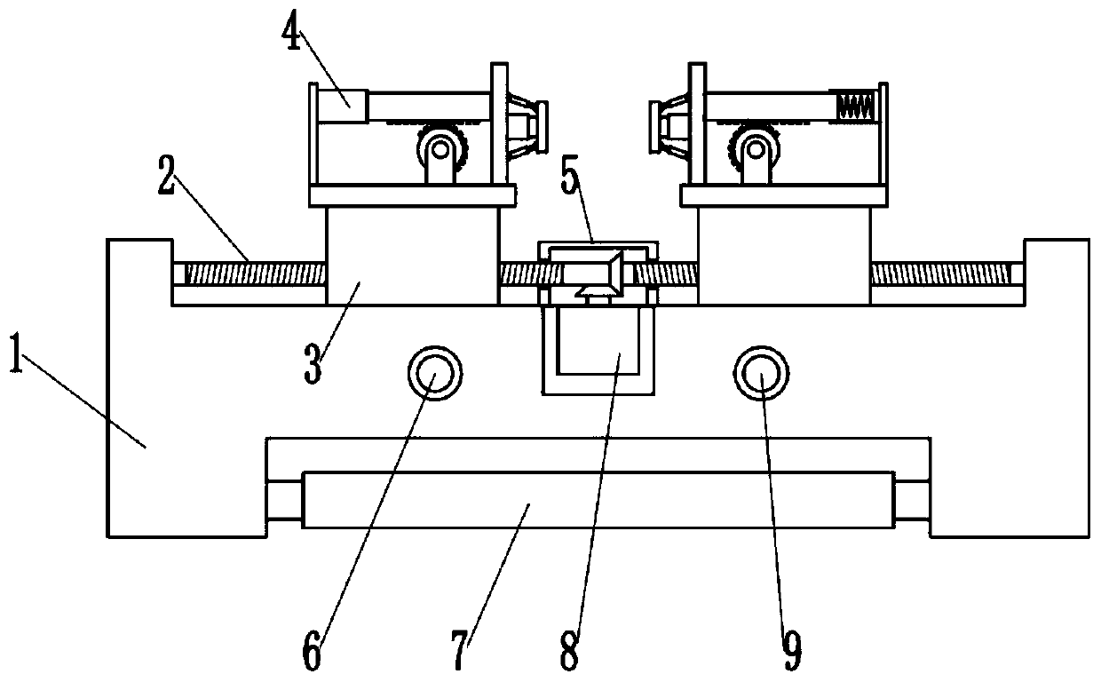
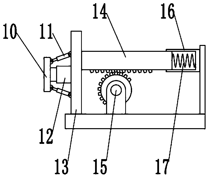
[0028] see Figure 1~4 , in an embodiment of the present invention, a network transformer pin pitch adjustment mechanism includes a body 1 and an adjustment mechanism 4; There are two kinds of external threads with opposite rotation symmetrically arranged, and two screw sleeves 3 are also symmetrically threaded on the left and right sides of the first adjusting screw 2, one side of the screw sleeve 3 is slidingly connected with the body 1, and through the first adjusting screw 2 The rotation drives the screw sleeve 3 to slide on the body 1, the other side of the screw sleeve 3 is fixedly connected with the adjustment mechanism 4, and the pins are adjusted through the adjustment mechanism 4;

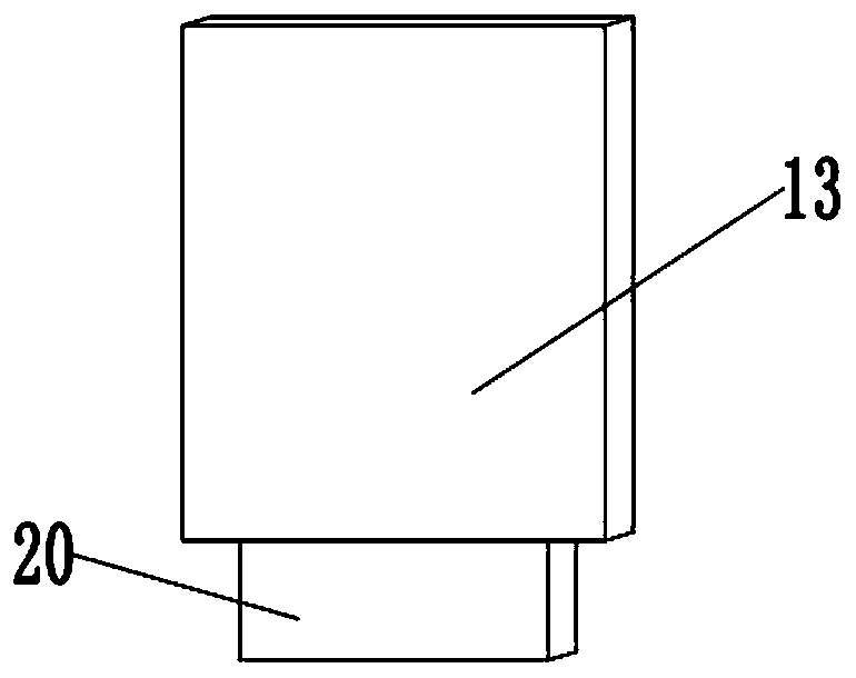
[0029] The adjustment mechanism 4 includes a mounting plate and a collision plate 10 horizontally installed on the screw sleeve 3, a push plate 13 is vertically installed on the end of the mounting plate towards the middle of the first adjusting screw 2, and a main push plate 13 is fixedl...

Embodiment 2

[0037] see Figure 5 , The difference between this embodiment and Embodiment 1 is that two second adjusting screw rods 22 are installed in the left and right symmetrical rotation inside the groove, and the ends of the two second adjusting screw rods 22 that are close to each other are threadedly connected with push rods. 23, the outer side of the push rod 23 is fixedly installed with a clamp 24, and the inside of the groove is also symmetrically installed with two limit brackets 25, the limit bracket 25 is slidably connected with the push rod 23, and is driven by rotating the second adjusting screw 22. The push rod 23 moves, so that the two clamps 24 are close to each other, so as to facilitate fixing on the bracket;

[0038] Specifically, in this embodiment, the second adjusting screw 22 is mounted with a knob 21 to drive it to rotate.


PUM


Abstract

The invention relates to the technical field of pin distance adjusting, in particular to a pin distance adjusting mechanism of a network transformer. The pin distance adjusting mechanism comprises a body and adjusting mechanisms, wherein the front side of the body is rotatably provided with a first adjusting screw rod, the left side and the right side of the first adjusting screw rod are symmetrically provided with two opposite external threads, the left side and the right side of the first adjusting screw rod are further symmetrically in threaded connection with two screw sleeves, and the other sides of the screw sleeves are fixedly connected with the corresponding adjusting mechanisms; and each adjusting mechanism comprises a mounting plate horizontally mounted on each screw sleeve and acollision plate, a push plate is vertically mounted at the end, facing the middle of the first adjusting screw rod, of each mounting plate, a main telescopic rod is fixedly installed on the outer side of each push plate, and the telescopic end of each main telescopic rod is fixedly connected with the corresponding collision plate. According to the pin distance adjusting mechanism, when pins are adjusted, a screw rod is driven to slide by rotating the first adjusting screw rod, and the adjusting mechanisms are moved to the proper positions; and then the lengths of the main telescopic rods areadjusted, the pins are squeezed by the collision plates, and the pins are forced to reset.

Description

technical field [0001] The invention relates to the technical field of pitch adjustment of pins, in particular to a mechanism for pitch adjustment of network transformers. Background technique [0002] With the continuous development of science and technology, the application of integrated circuits has become more and more extensive. As related electronic devices tend to develop in the direction of light and thin appearance, when most of the electronic components are packaged in SMD (Surface Mounted Devices, Surface Mounted Devices) and their volumes are all certain, printed circuit boards are used as integrated circuits and their electronic components. Carriers have always attracted people's attention. [0003] Pins, also known as pins, are called Pins in English. It is the connection between the internal circuit of the integrated circuit (chip) and the peripheral circuit, and all the pins constitute the interface of this chip. A section of the end of a lead that is sold...

Claims


Application Information

Patent Timeline
IPC IPC(8): B21F1/02H01F41/00
CPCB21F1/02H01F41/00
Inventor 陈小勇朱千林杨艳军
Owner LEIYANG YAXIANG ELECTRONICS TECH
Learn More