Supercharge Your Innovation With Domain-Expert AI Agents!

Anti-collision structure for front end of railway vehicle chassis

A rail vehicle and underframe technology, applied in the field of rail vehicle underframe structure design, can solve problems such as threatening passenger safety and poor vertical load capacity, and achieve the effects of weight reduction, ingenious force transmission, and compact structure design.

Active Publication Date: 2020-03-27
CRRC NANJING PUZHEN CO LTD
View PDF9 Cites 1 Cited by
  • Summary
  • Abstract
  • Description
  • Claims
  • Application Information

AI Technical Summary

Problems solved by technology

However, the vertical load capacity of this structure is poor, and once the car climbs, the vertical force is transmitted to the underframe through the end beam, threatening the safety of passengers

Method used


Image

  • Anti-collision structure for front end of railway vehicle chassis
  • Anti-collision structure for front end of railway vehicle chassis
  • Anti-collision structure for front end of railway vehicle chassis

Examples


Embodiment Construction

[0017] Embodiments of the present invention will be explained below in conjunction with the accompanying drawings.

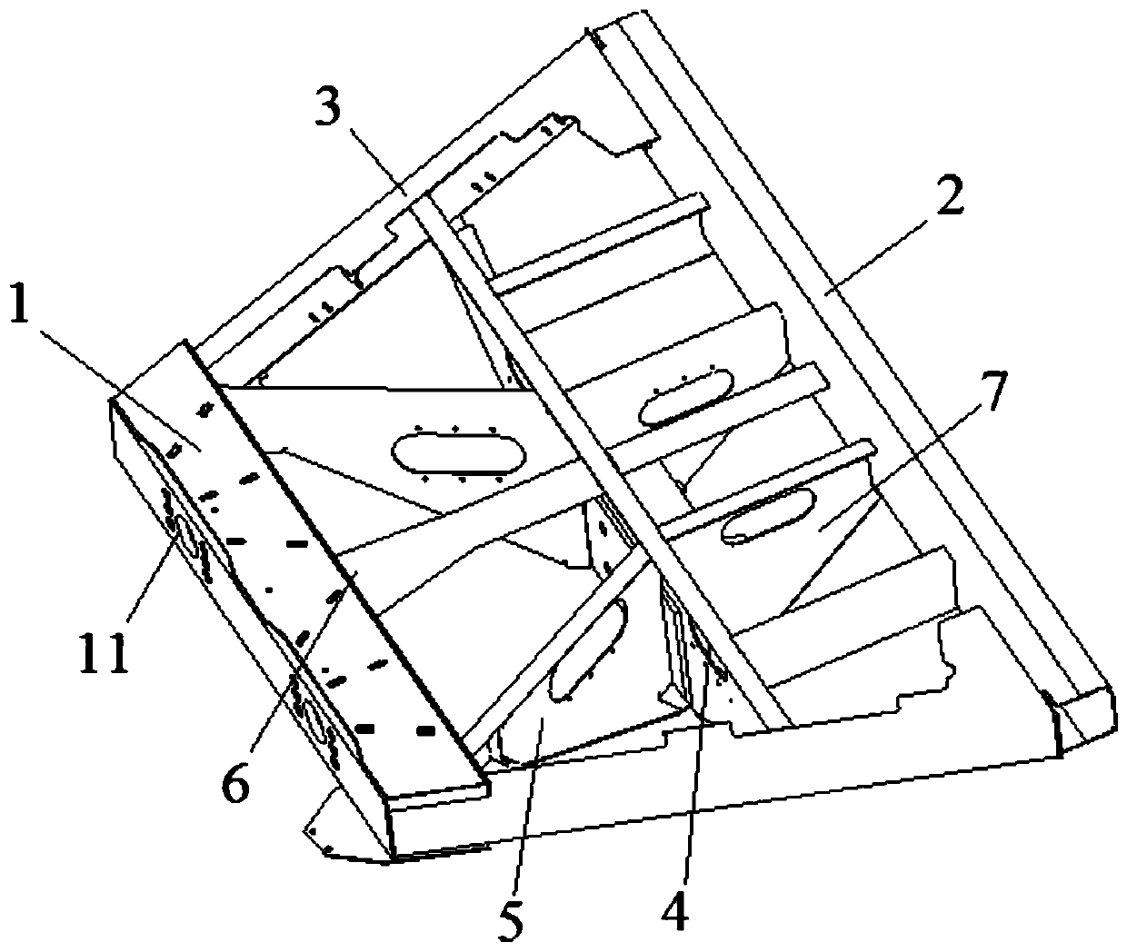
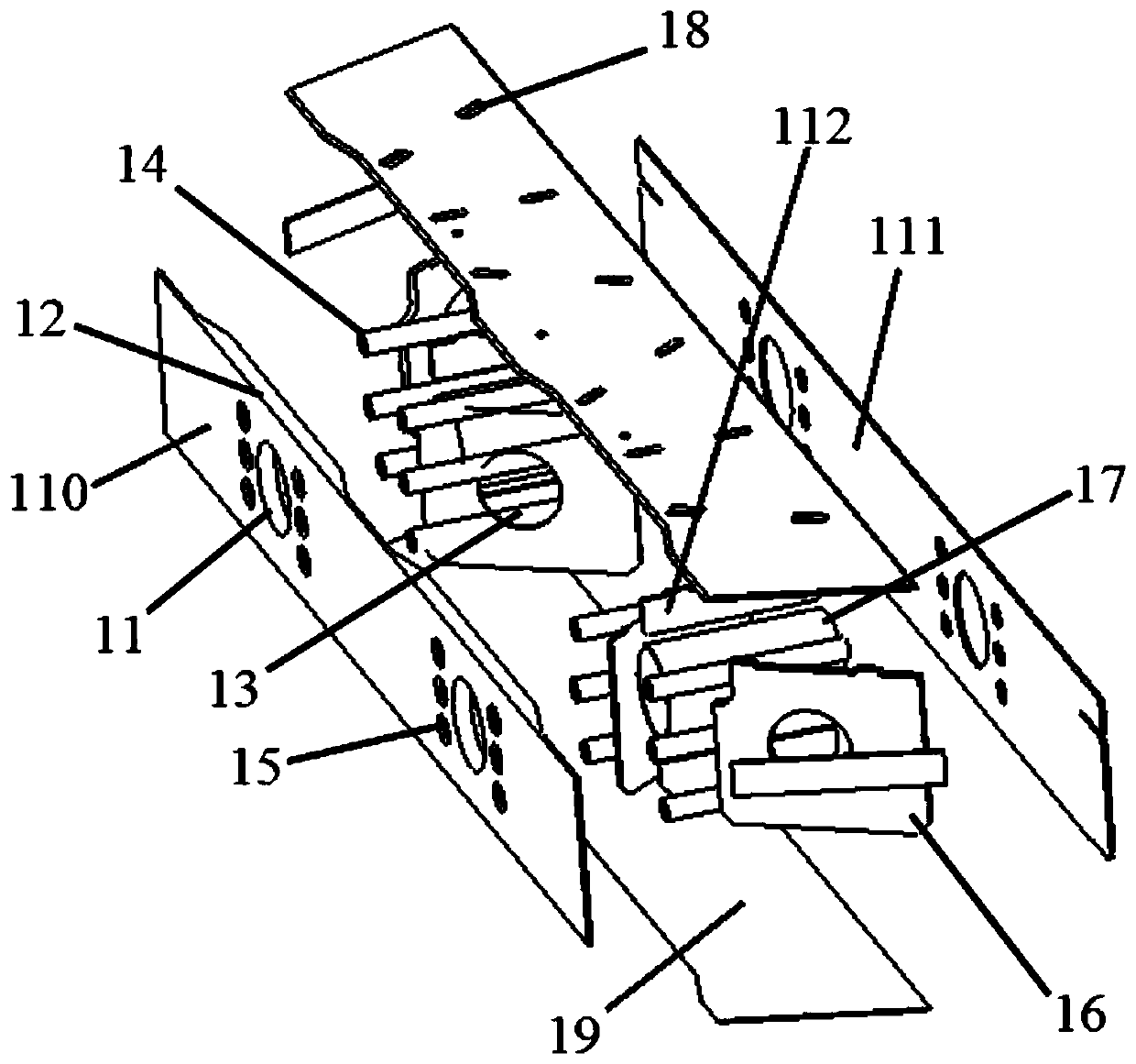
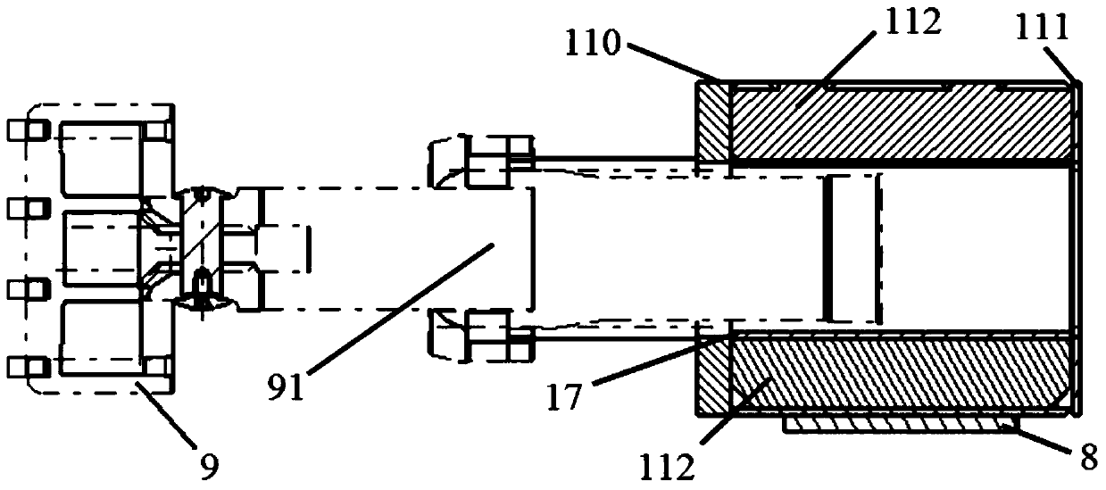
[0018] Such as Figure 1 to Figure 5 As shown, the anti-collision structure at the front end of the rail vehicle underframe in this embodiment includes an end beam 1, a side beam 3, a buffer beam 2 and a coupler installation beam 4, and two inclined beams 5 are welded between the end beam 1 and the coupler installation beam 4, An 80° angle with the opening forward is formed between the two slanting beams 5 (the range of the angle is 60°-90°), and the longitudinal impact force is transmitted through the two slanting beams. A front variable section beam 6 is welded between the middle part of the installation beam 4 and the middle part of the end beam 1 , and a rear variable section beam 7 is welded between the coupler installation beam 4 and the buffer beam 2 . The inclined beam 5 and the rear variable cross-section beam 7 are provided with lightening holes, and ...


PUM


Abstract

The invention relates to an anti-collision structure for the front end of a railway vehicle chassis. The structure comprises an end beam, a boundary beam, a buffer beam and a coupler mounting beam, the end beam is of a box-shaped structure with a mounting beam, a back plate, an upper cover plate and a lower cover plate. The mounting beam is provided with a mounting hole for a guide pipe of an anti-creeper to pass through; bolt holes are formed around the mounting hole; the area, around the mounting hole, of the mounting beam is thickened. A guide cylinder and a bolt mounting pipe arranged on the mounting beam and the back plate are arranged in the end beam, the front ends of the guide cylinder is in butt joint with the mounting hole, the front end of the bolt mounting pipe is in butt jointwith the bolt hole, oblique rib plates are further arranged in the end beam, and the outer ends of the mounting beam, the upper cover plate and the lower cover plate are welded. The anti-creeper mounting structure is compact in structural design and ingenious in force transmission mode, the weight of the anti-creeper mounting structure (end beam) is reduced due to the lightweight design that lightening holes are additionally formed in internal rib plates, 400 KN longitudinal force can be effectively borne, and 200 KN vertical force cannot be yielded.

Description

technical field [0001] The invention relates to a front end structure of a rail vehicle underframe and belongs to the technical field of rail vehicle underframe structure design. Background technique [0002] With the development of rail vehicle technology, the requirements for vehicles are getting higher and higher. Not only the car body structure is required to be easy to assemble, the installation interface of the equipment is reasonable, but also it is required to be able to withstand large longitudinal forces. [0003] In the actual vehicle-to-vehicle collision conditions, the most important thing is the anti-climbing function of the vehicle. Once "climbing" occurs, the energy-absorbing area at the end of the vehicle cannot play a deformation buffer role, and the vehicle will be seriously damaged, threatening the safety of passengers. The design of the vertical strength of the anti-climbing device installation structure at the front end of the chassis is particularly i...

Claims


Application Information

Patent Timeline
IPC IPC(8): B61F1/08B61F1/10B61F19/04
CPCB61F1/08B61F1/10B61F19/04
Inventor 高健飞徐涛董静胡基贵刘英博鲍伟兵
Owner CRRC NANJING PUZHEN CO LTD
Features
  • R&D
  • Intellectual Property
  • Life Sciences
  • Materials
  • Tech Scout
  • Unparalleled Data Quality
  • Higher Quality Content
  • 60% Fewer Hallucinations
Learn More