Steel box girder reinforcing structure and method

A technology for strengthening structures and steel box girders, which is used in bridge reinforcement, bridges, bridge maintenance, etc. It can solve the problem that the improvement effect of crack tip stress is difficult to evaluate, reduce structural rigidity and ultimate bearing capacity, and improve the stress of diaphragm base material. and other problems, to achieve the effect of convenient reinforcement design and construction, inhibition of crack propagation, simple and lightweight structure

Pending Publication Date: 2018-06-01
CHANGSHA UNIVERSITY OF SCIENCE AND TECHNOLOGY
View PDF5 Cites 3 Cited by
  • Summary
  • Abstract
  • Description
  • Claims
  • Application Information

AI Technical Summary

Problems solved by technology

The improved geometry method may reduce the stiffness and ultimate bearing capacity of the structure, which is not applicable to long cracks
The additional bolt holes added by the bolted steel plate method will cause new damage to the diaphragm and increase the weight greatly. It is difficult to evaluate the effect of improving the crack tip stress. It is necessary to formulate reinforcement schemes for different crack directions one by one, which brings great difficulties to design and construction. big difficulty
Although the newly developed UHPC method can significantly reduce the fatigue stress of the bridge deck and its connection details with the U-rib, it does not improve the stress amplitude of the parent material of the diaphragm at the arc-shaped cut away from the bridge deck much, and the cost is high

Method used


Image

  • Steel box girder reinforcing structure and method
  • Steel box girder reinforcing structure and method
  • Steel box girder reinforcing structure and method

Examples


Embodiment 1

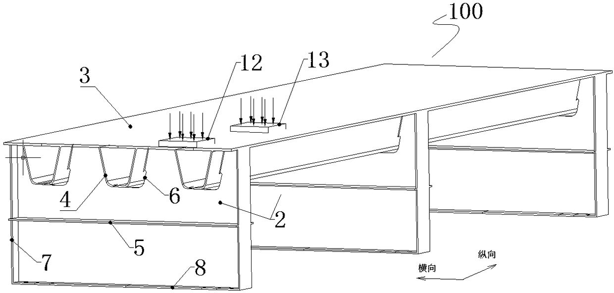
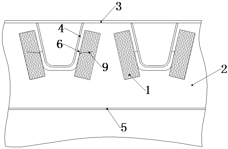
[0052] like Figure 1~3 As shown, a steel box girder reinforcement structure includes a box girder body 100, and the box girder body 100 includes a transverse diaphragm 2 arranged at intervals, a top plate 3, a bottom plate 8, and vertical stiffeners 7 arranged perpendicular to both ends of the bottom plate 8 , the through notch 21 opened on the transverse partition plate 2 , and the U rib 4 fixed in the notch 21 . The diaphragm 2 is fixed on the bottom plate 8 and fixed between two vertical stiffeners 7 . The top plate 3 is fixed on the top of the U-rib 4 and the vertical stiffener 7 , and a horizontal stiffener 5 is provided in the middle of the diaphragm 2 .

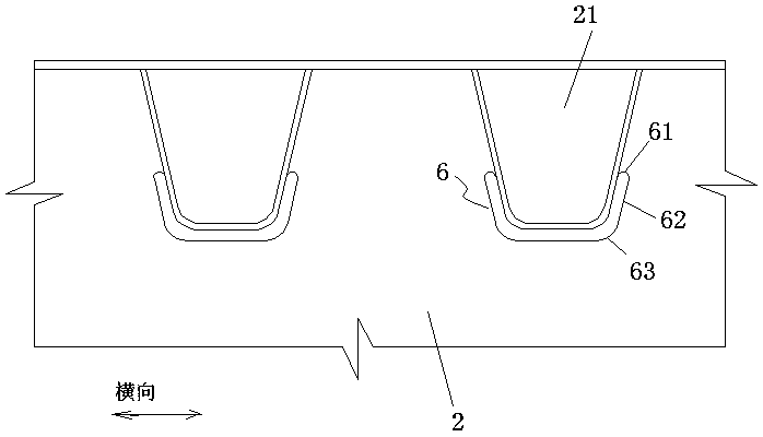
[0053] Arc-shaped notches 6 are formed on both sides of the notch 21 , and there is a gap between the edges of the arc-shaped notches 6 and the U rib 4 . The arc-shaped notch 6 includes an upward convex arc section 61 extending laterally on the side of the notch 21, an oblique edge section 62 connected with the upwa...

Embodiment 2

[0079] like Figure 7 As shown, Example 1 is repeated, the difference is that the reinforcing plate 1 is a special-shaped plate, and is a laminated plate, including a first plate 10 for being arranged between two adjacent arc-shaped gaps 6, And the second plate 11 for being arranged on one side of the arc-shaped notch 6 . The shapes of both sides of the first plate 10 match the shape of the arc-shaped notch 6 . Only one side of the second plate 11 matches the shape of the arc-shaped notch 6 .

[0080] The first plate 10 is suitable for the situation that the regions of the diaphragm 2 near two adjacent arc-shaped notches 6 need to be reinforced. The second plate 11 is suitable for the situation where only one area of ​​the diaphragm 2 near the arc-shaped notch 6 needs to be reinforced.

Embodiment 3

[0082] like Figure 8-9As shown, repeat Example 2, the difference is: the bolt 15 between the reinforcing plate 1 and the diaphragm 2 is reinforced twice with the annular steel gasket 14, and the annular steel gasket 14 is pressed on the reinforcing plate 1 four corners, and fastened to the diaphragm 2 with bolts 15.


PUM


Abstract

The invention discloses a steel box girder reinforcing structure and method. The steel box girder reinforcing structure comprises a box girder body. The box girder body comprises transverse partitionplates arranged at intervals and groove openings running through the transverse partition plates. Arc-shaped notches are formed in the two lateral sides in each groove opening. Each arc-shaped notch has an area with fatigue cracking risks or even fatigue cracks. Reinforcing plates are arranged on the side faces of each transverse partition plate. By reinforcing the areas with fatigue cracking risks or even fatigue cracks of the transverse partition plates, the local rigidity of the arc-shaped notches of the transverse partition plates is remarkably improved, the production of the fatigue cracks can be restrained or delayed or the expansion of the cracks can be effectively restrained, and the fatigue service life is greatly prolonged. Moreover, by means of the reinforcing method, no new damage is caused to the original structure of the transverse partition plates, the structure is simple, and construction is convenient.

Description

technical field [0001] The invention belongs to the technical field of bridge engineering, and in particular relates to a steel box girder reinforcement structure and a reinforcement method thereof. Background technique [0002] Orthotropic deck steel box girders are widely used in the construction of large and medium-sized bridges. The structure of steel box girders includes diaphragms arranged at intervals, top slabs, bottom slabs, vertical stiffeners arranged perpendicular to both ends of the bottom slab, The through notch opened, the U rib fixed in the notch, the transverse partition plate is fixed on the bottom plate and fixed between the two vertical stiffeners, the top plate is fixed on the top of the U rib and the vertical stiffener, A horizontal stiffener is provided in the middle of the diaphragm. There are arc-shaped notches on both sides of the notch, and there is a gap between the edge of the arc-shaped notch and the U rib. Usually, the two sides of the U rib ...

Claims


Application Information

Patent Timeline
Patent Type & Authority Applications(China)
IPC IPC(8): E01D22/00
CPCE01D22/00
Inventor 李传习柯璐陈卓异王新忠曹先慧罗南海
Owner CHANGSHA UNIVERSITY OF SCIENCE AND TECHNOLOGY
Why Eureka
Try Eureka