Cast-in-place joint structure of UHPC beam plate with embedded reinforcing steel components and construction method thereof

A technology of pre-embedded steel bars, beams and slabs, used in bridges, bridge parts, bridge construction, etc., can solve the problems of poor tensile performance of ultra-high performance concrete, affecting structural durability and service performance, and failing to meet design requirements. Achieve rapid construction, solve weak connection force, improve crack resistance and overload resistance

Active Publication Date: 2020-09-25
HUNAN UNIV
View PDF23 Cites 3 Cited by
  • Summary
  • Abstract
  • Description
  • Claims
  • Application Information

AI Technical Summary

Problems solved by technology

However, the fibers at the cast-in-place joints of UHPC bridge decks are discontinuous and separated, resulting in relatively poor tensile properties of UHPC at the joints
The bridge deck is prone to cracking under the repeated action of the local wheel load of the vehicle, which cannot meet the design requirements
In addition, due to the ultra-low water-binder ratio and high amount of cementitious materials, the total shrinkage of ultra-high performance concrete is higher than that of ordinary concrete or high-performance concrete, and the development of early shrinkage is faster, resulting in the prefabricated ultra-high performance concrete bridge deck and existing The joint interface of poured ultra-high performance concrete (that is, the interface of new and old ultra-high performance concrete) is prone to shrinkage cracks, causing water seepage on the bridge deck, affecting the durability and performance of the structure
In addition, the existing joint construction needs to be chiseled, and the construction process is relatively complicated

Method used


Image

  • Cast-in-place joint structure of UHPC beam plate with embedded reinforcing steel components and construction method thereof
  • Cast-in-place joint structure of UHPC beam plate with embedded reinforcing steel components and construction method thereof
  • Cast-in-place joint structure of UHPC beam plate with embedded reinforcing steel components and construction method thereof

Examples


Embodiment 1

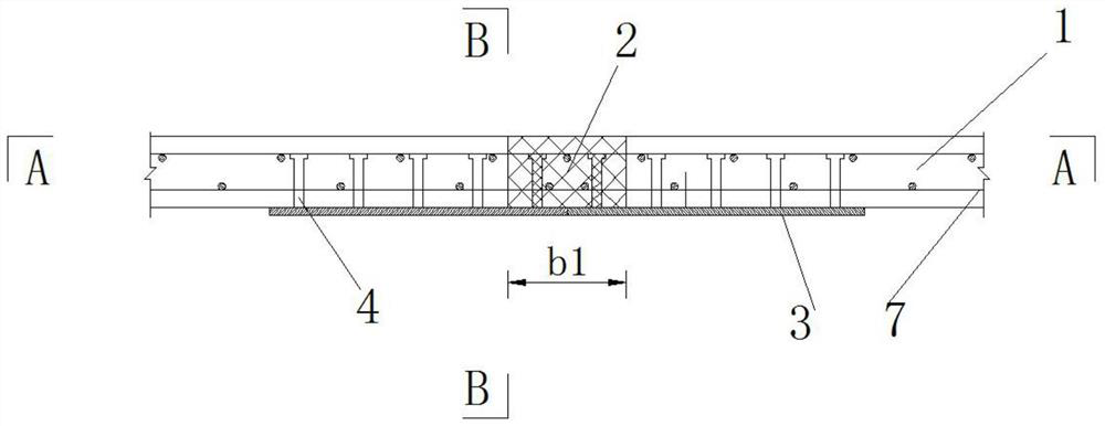
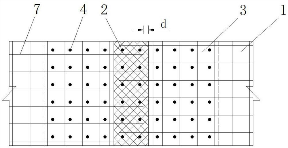
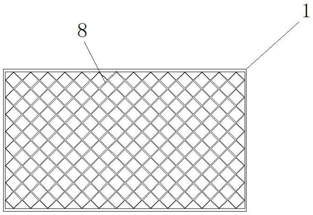
[0044] Such as Figure 1-Figure 3 As shown, the UHPC beam-slab cast-in-place joint structure with pre-embedded reinforced steel parts in this embodiment includes a pair of adjacent prefabricated UHPC beams Casting UHPC joint 2, the bottom of prefabricated UHPC beam slab 1 is fixed with pre-embedded reinforced steel part 3 extending to cast-in-situ UHPC joint 2, and the ends of adjacent pre-embedded reinforced steel parts 3 are fixed; prefabricated UHPC beam slab The side wall at the end of 1 is provided with grid-shaped grooves 8, and the steel fibers in the UHPC are exposed in the grid-shaped grooves 8.

[0045] In this embodiment, the pre-embedded reinforced steel part 3 is a patterned steel plate, and the surface of the patterned steel plate is provided with a shear connector 4, and the pre-embedded reinforced steel part 3 is fixedly connected with the prefabricated UHPC beam plate 1 through the shear connector 4 to form a whole. The shear connector 4 is in the form of a c...

Embodiment 2

[0056] Such as Figure 4 As shown, the difference between this embodiment and Embodiment 1 is that the embedded reinforced steel part 3 is a corrugated steel plate, and the surface of the corrugated steel plate is provided with a shear connector 4, and the embedded reinforced steel part 3 is connected to the The prefabricated UHPC beam slab 1 is fastened into a whole. The shear connector 4 is in the form of a cylindrical head welding stud with a diameter of 0.013m, a length of 0.15m, and a spacing of 0.15m.

Embodiment 3

[0058] Such as Figure 5-6 As shown, the difference between this embodiment and Embodiment 1 is that the embedded reinforced steel part 3 is a T-shaped steel, and the T-shaped steel includes a bottom plate 9 and a plurality of parallel and spaced pieces fixed on the bottom plate 9. The web 5 is provided with evenly distributed circular holes 6 , and the bottom plate 9 is fixedly connected with the prefabricated UHPC beam 1 through the web 5 to form a whole.


PUM


Abstract

The invention discloses a cast-in-place joint structure of a UHPC beam plate with embedded reinforcing steel components. The structure comprises a pair of adjacently-arranged prefabricated UHPC beam plates and a cast-in-place UHPC joint cast in place between the pair of prefabricated UHPC beam plates, wherein the bottom of each prefabricated UHPC beam plate is fixedly provided with an embedded reinforcing steel component extending to the cast-in-place UHPC joint, and the end parts of the adjacent embedded reinforcing steel components are fixedly connected; and the side wall of the end part ofthe prefabricated UHPC beam plate is provided with a latticed groove. The invention further provides a construction method of the cast-in-place joint structure of the UHPC beam plate with the embeddedreinforcing steel components. According to the invention, through the mutual synergistic effect of the latticed grooves and the embedded reinforced steel components, the latticed grooves and the embedded reinforced steel components are mutually matched, so that the problem of weak stress of the UHPC bridge deck wet joint connection can be effectively solved, the stress performance of the new andold UHPC interfaces is remarkably improved, the interfaces cannot crack under the action of service load, and the durability and the service performance of the structure are improved.

Description

technical field [0001] The invention belongs to the field of bridge structure construction, and in particular relates to a UHPC beam-slab cast-in-place joint and a construction method thereof. Background technique [0002] Ultra-high performance concrete (UHPC) is a fiber-reinforced cement-based composite material with a compressive strength exceeding 120 MPa and a tensile strength exceeding 6 MPa. "Ultra-high performance concrete" contains ultra-high durability and ultra-high mechanical properties, which can reduce the size of the structure, reduce the self-weight of the structure, improve the effectiveness of the structure to resist loads and increase the span of the structure, so it has a unique role in bridge structures. Wide application prospects. UHPC materials can show more excellent performance after high-temperature steam curing, so it is advisable to give priority to the use of factory prefabrication and then on-site installation to ensure the construction quality...

Claims


Application Information

Patent Timeline
Patent Type & Authority Applications(China)
IPC IPC(8): E01D19/12E01D21/00
CPCE01D19/125E01D21/00
Inventor 邵旭东邱明红晏班夫
Owner HUNAN UNIV
Why Eureka
Try Eureka