
Material carrying device with lifting function

A technology for handling devices and materials, which is applied in the direction of transportation and packaging, conveyor objects, conveyors, etc., which can solve the problems of production inconvenience and achieve the effect of lifting function

Inactive Publication Date: 2020-03-27
湖南沃峰智能科技有限公司
View PDF7 Cites 0 Cited by
  • Summary
  • Abstract
  • Description
  • Claims
  • Application Information

AI Technical Summary

Problems solved by technology

[0002] In the actual workshop production, it sometimes involves material handling between fixed-point distances or positions in the workshop. Under the existing technology, it is generally transported by trolleys or conveyed by conveyor lines. However, when height adjustment is involved, special equipment is required. The crane is running, which brings inconvenience to the actual production

Method used


Image

  • Material carrying device with lifting function
  • Material carrying device with lifting function
  • Material carrying device with lifting function

Examples


Embodiment 1

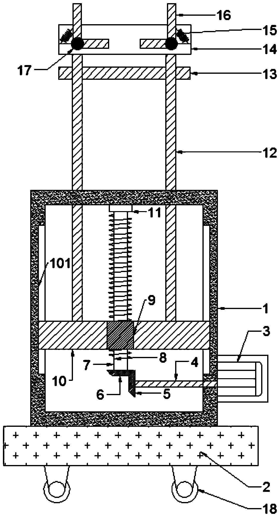
[0021] see Figure 1~3 , in an embodiment of the present invention, a lifting material handling device includes a housing 1 and a base 2, and also includes a lifting assembly and a transmission assembly. The lifting assembly includes a motor 3, a rotating shaft 4, a first bevel gear 5, a second bevel gear 6. Turning rod 7, thread 8, sliding block 9, sliding rod 10, upper fixing block 11, fixing rod 12 and mounting rod 13, housing 1 is set on base 2, motor 3 is fixedly installed on the outside of the side wall of housing 1 , the output end of the motor 3 is located inside the housing 1 and the rotating shaft 4 is installed, the outermost end of the rotating shaft 4 is installed with the first bevel gear 5, the first bevel gear 5 and the second bevel gear 6 are connected through gear fit, the second bevel gear The top of 6 is connected with the rotating rod 7, and the upper part of the rotating rod 7 is fixedly installed in the inside of the housing 1 through the upper fixed blo...

Embodiment 2

[0027] In order to diversify the functions of the lifting material handling device, this embodiment is further improved on the basis of Embodiment 1. Two fixed rods 12 above the mounting rod 13 are provided with mounting plates 14; Two fixed rods 12 are provided with mounting plates 14, so that goods can be stored on the mounting plates 14, which is convenient for the staff at high places to carry out further work.

[0028] A limiting plate 16 is installed above the mounting plate 14, and the bottom end of the limiting plate 16 is connected with the mounting plate 14 by a hinge 17, and the top of the limiting plate 16 is connected with the mounting plate 14 by the first elastic member 15; A limiting plate 16 is installed above the mounting plate 14, and the bottom end of the limiting plate 16 is connected with the mounting plate 14 by a hinge 17, and the top of the limiting plate 16 is connected with the mounting plate 14 by the first elastic member 15, and the mounting plate 1...


PUM


Abstract

The invention discloses a material carrying device with a lifting function. The material carrying device with the lifting function comprises a shell and a base, and further comprises a lifting assembly and a conveying assembly, wherein the lifting assembly comprises a motor, a rotating shaft, a first bevel gear, a second bevel gear, a rotating rod, threads, a sliding block, a sliding rod, an upperfixing block, a fixing rod and a mounting rod, the conveying assembly comprises a first mounting plate, a second mounting plate, a first rotating wheel, a second rotating wheel, a third rotating wheel, a lower fixing block, a connecting rod, a second elastic piece, a rotating rod and a mounting block, the lower fixing block is mounted on the side wall of the lowermost end of the first mounting plate, the lower fixing block is hinged to one end of the connecting rod, the other end of the connecting rod is provided with the third rotating wheel, the upper surface of the connecting rod is connected with the lower surface of the first mounting plate through the second elastic piece, a conveying belt is arranged on the outer sides of the first rotating wheel, the second rotating wheel and thethird rotating wheel in a sleeving mode, the conveying belt is always in a tensioned state so that goods can always be in the conveyed state, and the lifting function of the material carrying device is achieved.

Description

technical field [0001] The invention relates to a handling device, in particular to a lifting material handling device. Background technique [0002] In the actual workshop production, it sometimes involves material handling between fixed-point distances or positions in the workshop. Under the existing technology, it is generally transported by trolleys or conveyed by conveyor lines, but when it comes to height adjustment, special equipment is also required. The crane is running, which brings inconvenience to the actual production. In order to solve the above-mentioned problems, the present invention proposes a lifting material handling device. Contents of the invention [0003] The object of the present invention is to provide an elevating material handling device to solve the problems raised in the above-mentioned background technology. [0004] To achieve the above object, the present invention provides the following technical solutions: [0005] A lifting material h...

Claims


Application Information

Patent Timeline
IPC IPC(8): B65G21/12B65G41/00B65G23/44B65G15/28
CPCB65G15/28B65G21/12B65G23/44B65G41/008B65G2812/02217
Inventor 刘绍亚吴继春王红辉熊任上王晟垚
Owner 湖南沃峰智能科技有限公司
Features
  • Generate Ideas
  • Intellectual Property
  • Life Sciences
  • Materials
  • Tech Scout
  • Unparalleled Data Quality
  • Higher Quality Content
  • 60% Fewer Hallucinations
Learn More