
Gate valve

A technology for flapper valves and cover plates, which is applied to sliding valves, valve devices, engine components, etc., can solve problems such as poor sealing effect, and achieve the effect of improving the sealing effect

Pending Publication Date: 2020-03-27
WUHAN KERUIDA VACUUM TECH CO LTD
View PDF0 Cites 0 Cited by
  • Summary
  • Abstract
  • Description
  • Claims
  • Application Information

AI Technical Summary

Problems solved by technology

[0006] Aiming at the technical problems existing in the prior art, the present invention provides a flapper valve to solve the problem of poor sealing effect

Method used


Image

  • Gate valve
  • Gate valve
  • Gate valve

Examples


Embodiment 1

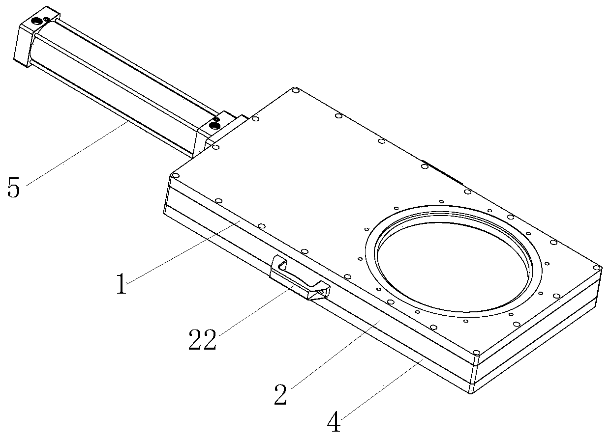
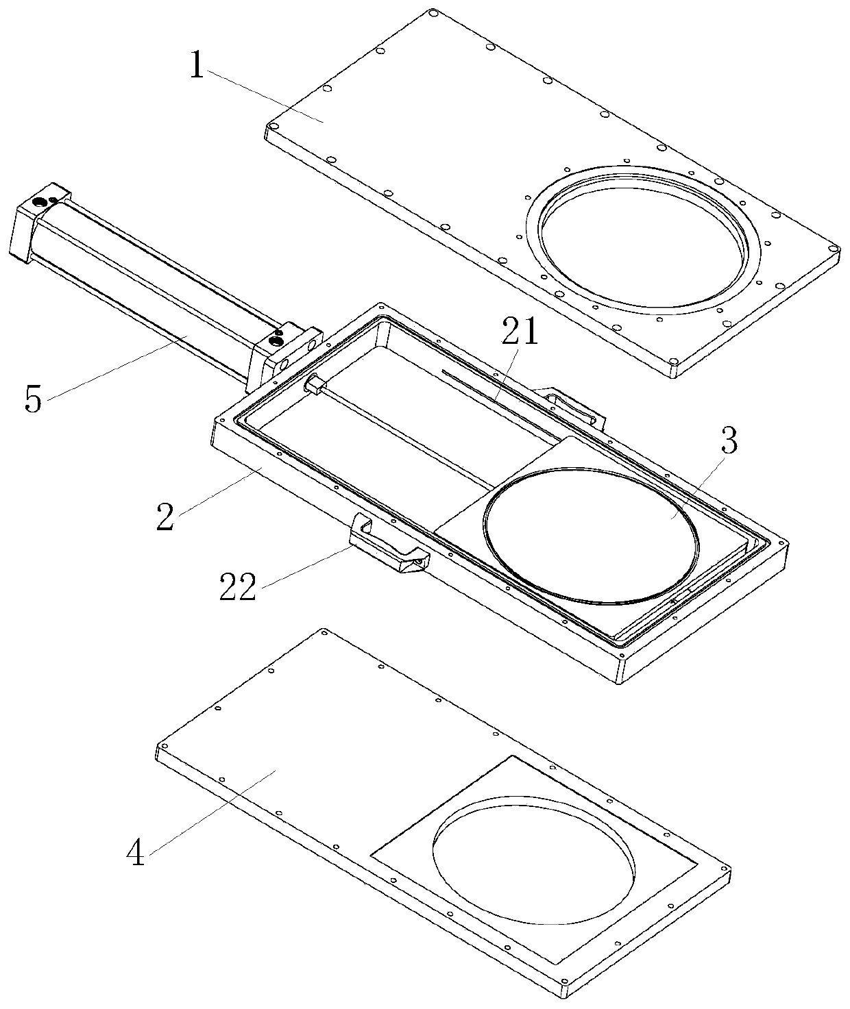
[0033] Such as Figure 1 to Figure 7 As shown, a flapper valve described in this embodiment includes an upper cover plate 1, a valve body seat 2, a walking and sealing device 3, a lower cover plate 4, and a cylinder 5; the upper cover plate 1, the valve body seat 2 And the lower cover plate 4 is used to be installed between the vacuum pump and the coating machine cavity; the cylinder 5 is used to push the walking and sealing device 3; the walking and sealing device 3 is slidably connected with the valve body seat 2;

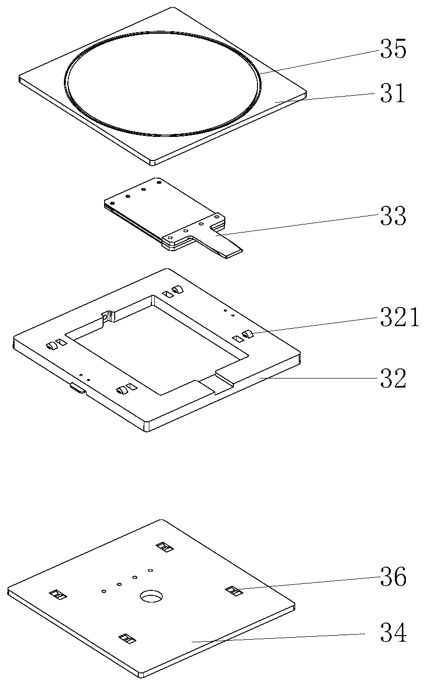
[0034] The walking and sealing device 3 includes an upper plate 31, an outer frame 32, an inner frame 33 and a lower plate 34; a sealing ring 35 is arranged in the sealing ring groove on the surface of the upper plate 31 and the lower plate 34; the outer frame 32 Linked with the guide rod of the cylinder 5; the upper surface and the lower surface of the outer frame 32 are provided with a plurality of rollers 321, and the corresponding positions of the upper plate...


PUM


Abstract

The invention relates to a gate valve which comprises an upper cover plate, a valve seat, a walking and sealing device slidingly connected with the valve seat, a lower cover plate and a driving mechanism. The walking and sealing device comprises an upper plate, an outer frame, an inner frame and a lower plate. The driving mechanism is used for pushing the outer frame. Seal rings are arranged in aseal ring groove in the surface of the upper plate and a seal ring groove in the surface of the lower plate. The upper surface and the lower surface of the outer frame are provided with a plurality ofejecting-out mechanisms. The upper plate and the lower plate are provided with wedge-shaped grooves matched with the ejecting-out mechanisms. The inner frame comprises an upper elastic piece and a lower elastic piece. One end of the upper elastic piece is provided with a tongue part, and the other end of the upper elastic piece is fixedly connected with the upper plate. One end of the lower elastic piece is fixedly connected with the end, close to the tongue part, of the upper elastic piece, and the other end of the lower elastic piece is fixedly connected with the lower plate. The outer frame and the inner frame are in limiting fit through the tongue part. The seal ring on the surface of the upper plate and the seal ring on the surface of the lower plate are in close contact with the upper cover plate and the lower cover plate, strong sealing is realized, and the sealing effect of the gate valve is remarkably improved.

Description

technical field [0001] The invention relates to a plug valve. Background technique [0002] Swing valve, also known as manual knife gate valve, knife gate valve is a kind of valve whose gate and valve seat are always in close contact and sealed. Make the round opening on the ram board completely disengage and coincide with the diameter. The sealing structure of the gate valve can be divided into soft seal and hard seal structure. [0003] The opening and closing part of the electric plug-in valve is the gate, and the movement direction of the gate is perpendicular to the direction of the fluid. The gate valve can only be fully opened or fully closed, and cannot be used for adjusting the amount of throttling. The gate has two sealing surfaces. The most commonly used mode is that the two sealing surfaces of the gate valve form a wedge, and the wedge angle varies with the valve parameters. [0004] Vacuum evaporation, referred to as evaporation, refers to the process of evap...

Claims


Application Information

Patent Timeline
Patent Type & Authority Applications(China)
IPC IPC(8): F16K3/18F16K3/314
CPCF16K3/18F16K3/314
Inventor 郭爱云朱选敏
Owner WUHAN KERUIDA VACUUM TECH CO LTD
Learn More