Transformer mounting structure convenient to mount and mounting method thereof

An installation structure and transformer technology, applied in the field of transformers, can solve problems such as low accuracy and affecting the installation quality of transformers, and achieve the effect of preventing inconvenient rotation and reducing friction

Active Publication Date: 2020-03-27
四川广蜀电力工程有限公司
View PDF6 Cites 0 Cited by
  • Summary
  • Abstract
  • Description
  • Claims
  • Application Information

AI Technical Summary

Problems solved by technology

However, in actual installation, it is usually judged by human eyes whether the support frame is in a horizontal state, and the accuracy is not high, which affects the installation quality of the transformer

Method used


Image

  • Transformer mounting structure convenient to mount and mounting method thereof
  • Transformer mounting structure convenient to mount and mounting method thereof
  • Transformer mounting structure convenient to mount and mounting method thereof

Examples


Embodiment 1

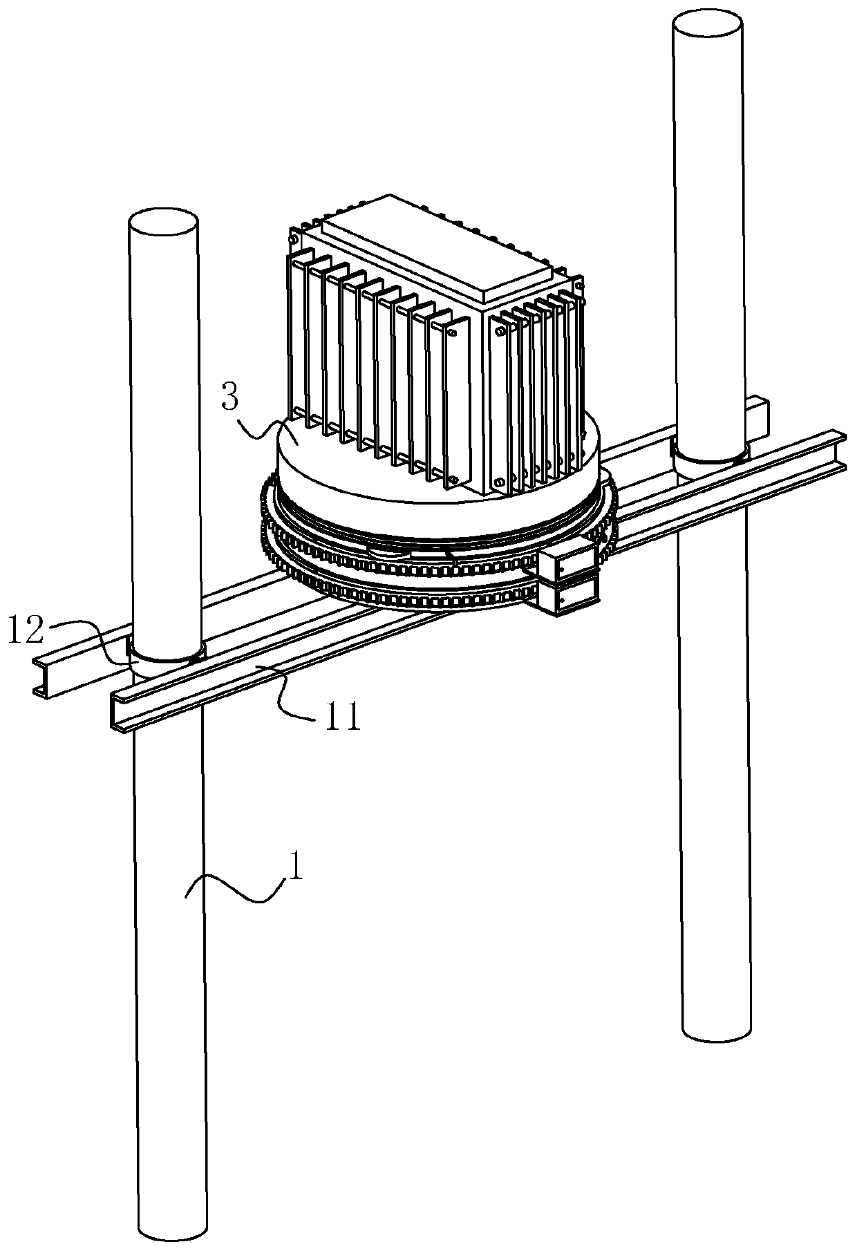
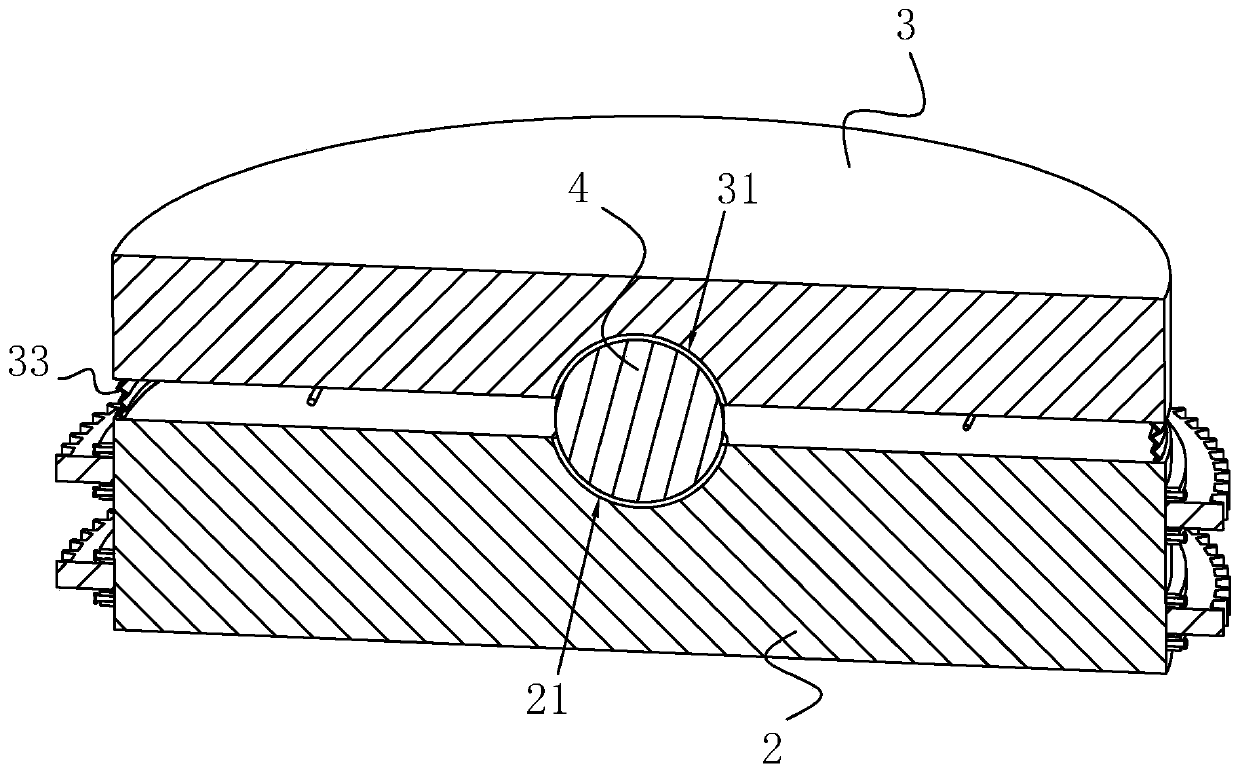
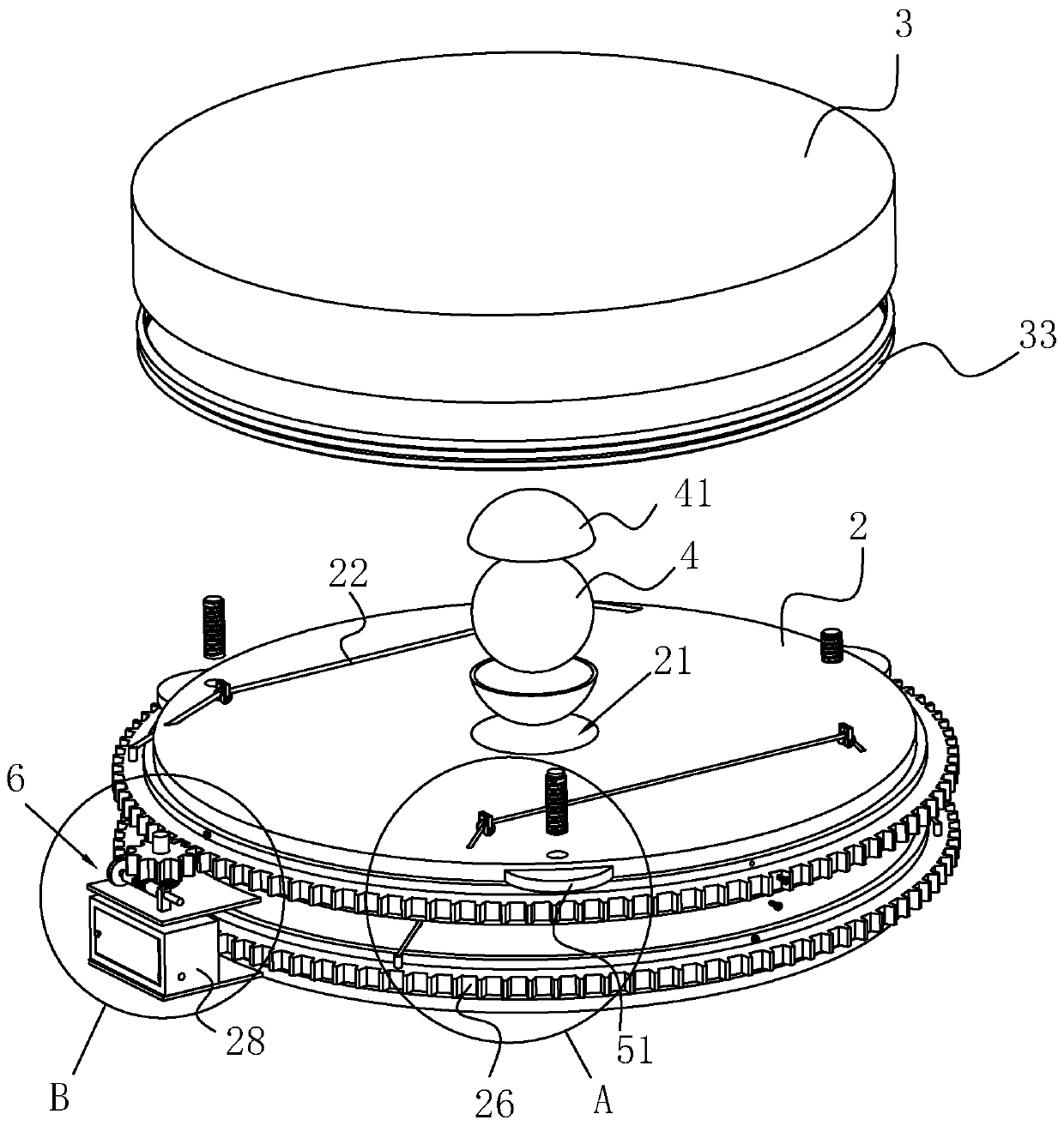
[0046] Such as figure 1 , 2 As shown, an easy-to-install transformer installation structure includes a base 2, a movable seat 3 and an adjusting ball 4. The adjusting ball 4 is a steel ball, and the cross section of the base 2 is circular. The top wall of the base 2 is provided with an arc-shaped first groove 21, the bottom wall of the movable seat 3 is provided with a second groove 31, and the adjusting ball 4 is rotatably embedded in the first groove 21 and the second groove 31. . The center of gravity of the movable seat 3 is on the same vertical line as the center of gravity of the adjusting ball 4; Leave space for the deflection of the movable seat 3 .

[0047] Such as figure 2 , 3 As shown, the first groove 21 and the second groove 31 are embedded with a polytetrafluoroethylene plate 41 bonded to the adjustment ball 4, the polytetrafluoroethylene plate 41 is an arc-shaped structure, and the polytetrafluoroethylene plate 41 adhere to the first groove 21 and the sec...

Embodiment 2

[0061] A transformer installation method for easy installation, comprising the following steps:

[0062] S1. Install the supporting frame 11, and fix the supporting frame 11 on the electric pole 1 through the hoop 12; the supporting frame 11 includes two channel steels.

[0063] S2. Lift the base 2 and the movable seat 3 together on the support frame 11, and then fix the base 2 on the support frame 11 by bolts.

[0064] S3. After the movable seat 3 is kept in balance, drive the support rod 5 to move upward through the adjustment member until the support rod 5 just abuts against the bottom wall of the movable seat 3, and after each support rod 5 abuts with the movable seat 3 , the position of the movable seat 3 is fixed by the fixture.

[0065] S4. Hoist the transformer on the movable seat 3, and fix it with the movable seat 3 through bolts.

[0066] After the base 2 is hoisted on the support frame 11, the base 2 is fixed on the support frame 11 by bolts. If the support frame...


PUM


Abstract

The invention relates to a transformer mounting structure convenient to mount and a mounting method thereof belonging to the technical field of transformers. The invention comprises a base, a movableseat and an adjusting ball, an arc-shaped first groove is formed in the top wall of the base, a second groove is formed in the bottom wall of the movable seat, the adjusting ball is rotatably embeddedin the first groove and the second groove, and the gravity center of the movable seat and the ball center of the adjusting ball are located on the same vertical line. Multiple supporting rods used for abutting against the movable base are arranged on the base in the vertical direction in a sliding and penetrating mode, the supporting rods are arranged in the circumferential direction of the baseat intervals, and an adjusting piece used for driving the supporting rods to move is arranged on the base. A fixing piece for limiting the position of the movable seat is arranged on the base. Duringconstruction, if the support frame is not horizontal, the movable seat deflects under the action of gravity and is automatically kept horizontal; thus, the purpose of horizontally installing the transformer is achieved, and installation quality is improved.

Description

technical field [0001] The invention relates to the technical field of transformers, in particular to a transformer installation structure and an installation method for easy installation. Background technique [0002] Transformer is a device that uses the principle of electromagnetic induction to change AC voltage. The main components are primary coil, secondary coil and iron core (magnetic core). Its main functions are: voltage conversion, current conversion, impedance conversion, isolation, voltage stabilization (magnetic saturation transformer), etc. [0003] The application publication number is CN109935443A, which is a transformer installation structure, including a pair of support frames fixed between two utility pole columns, one of which is located above the other support frame, which are respectively used to place the transformer and the control box. A pair of positioning slots are respectively opened on the two support frames, and the two positioning slots are op...

Claims


Application Information

Patent Timeline
Patent Type & Authority Applications(China)
IPC IPC(8): H01F27/02H01F27/06
CPCH01F27/06H01F27/02Y02E10/50
Inventor 鲜小康郭小龙申健
Owner 四川广蜀电力工程有限公司
Why Eureka
Try Eureka