Focusing lens for intelligent terminal camera, camera module and intelligent terminal
A camera module and smart terminal technology, applied in the field of cameras, can solve problems such as high camera height, shaking during focusing, and long focusing time
- Summary
- Abstract
- Description
- Claims
- Application Information
AI Technical Summary
Problems solved by technology
Method used
Image

Examples
Embodiment 1
[0034] The present invention proposes a focusing lens for a smart terminal camera.
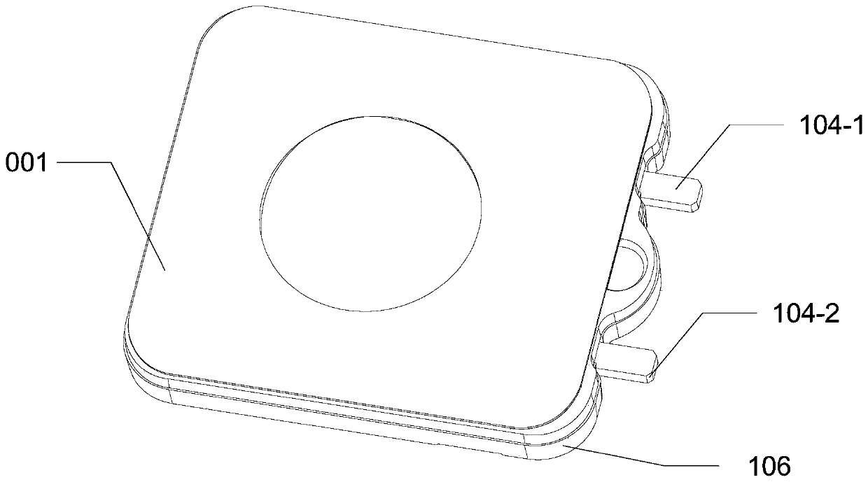
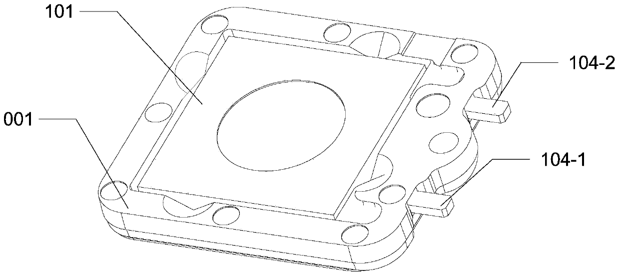
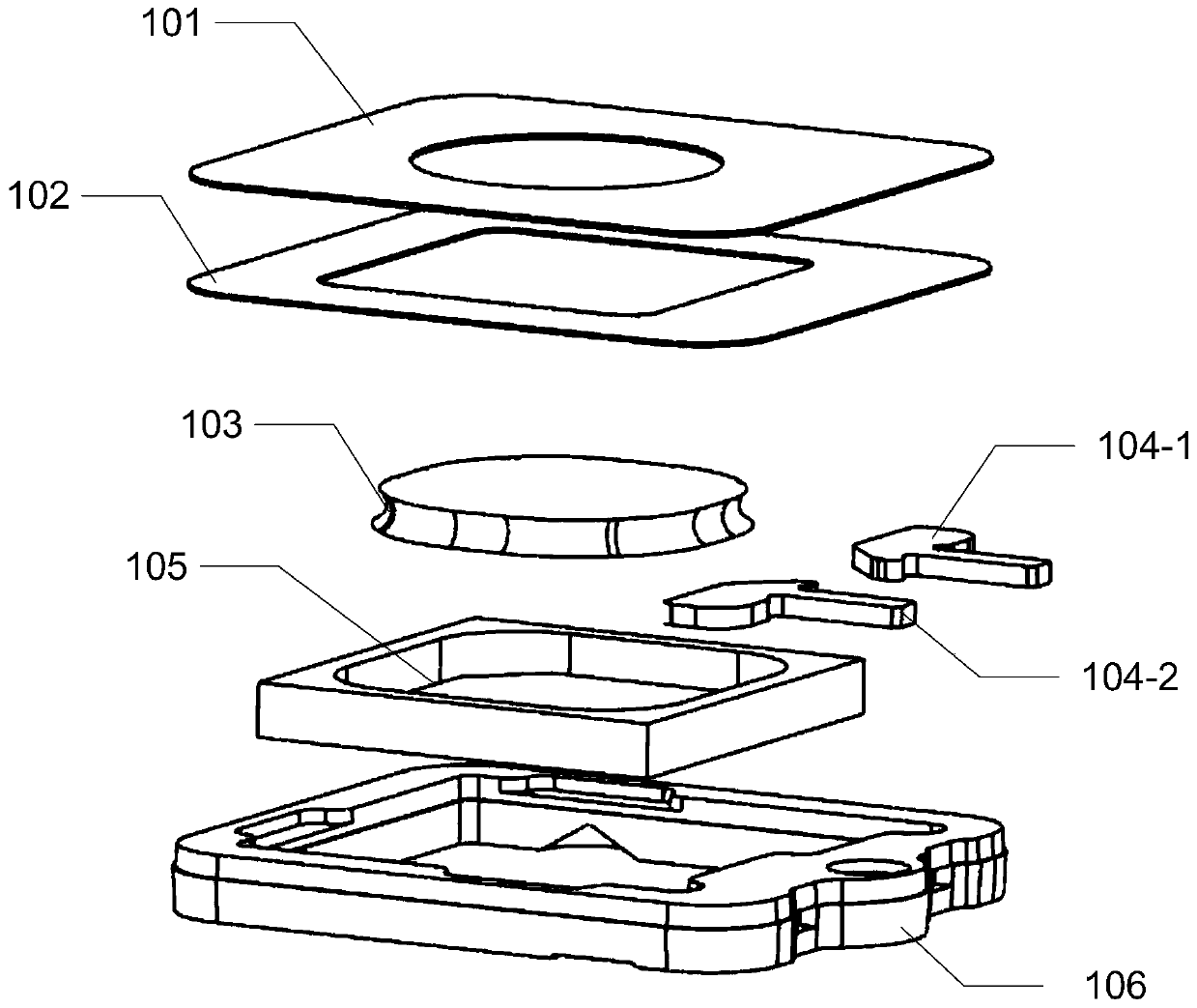
[0035] In the embodiment of the present invention, such as Figure 1-3 As shown, the focusing lens 001 for the smart terminal camera 003 includes: a main frame 106, a lower pole piece 105, a semi-solid material lens 103, an upper pole piece 102, a first wire 104-1, and a second wire 104-2 ; Wherein, the lower pole piece 105 is arranged in the main frame 106, the lower pole piece 105 is provided with an accommodation space 105-1, and the semi-solid material lens 103 is arranged in the accommodation space 105-1, The upper pole piece 102 is opposite to the lower pole piece 105, and the first wire 104-1 and the second wire 104-2 are respectively electrically connected to the upper pole piece 102 and the lower pole piece 105 for applying voltage, the lower pole piece 105 and the upper pole piece 102 deform under the voltage difference and drive the semi-solid material lens 103 to deform.
[0036]...
Embodiment 2
[0044] The present invention also proposes a camera module 1 for an intelligent terminal.
[0045] In this example, if Figure 4-5 As shown, the camera module 1 for the smart terminal includes: a frame body 002, a camera 003, and a focusing lens 001 for the smart terminal camera 003 in the first embodiment described above, and the focusing lens 001 is mounted on the frame body 002 On the camera 003, the camera 003 is electrically connected to the focusing lens 001.
[0046] The frame body 002 is fixedly arranged on the camera 003, the focusing lens 001 is fixedly arranged on the frame body 002, the focusing lens 001 is arranged on the frame body 002 for installing and setting the focusing lens 001, and the camera 003 and The focusing lens 001 is arranged correspondingly, so that the light path is transmitted to the camera 003 after passing through the focusing lens 001, and the image acquisition effect of the camera 003 can be improved. The camera 003 is electrically connect...
Embodiment 3
[0061] The invention also provides an intelligent terminal.
[0062] In this example, if Figure 8-9 As shown, the smart terminal includes: a casing 3 and the camera module 1 for the smart terminal as described in the second embodiment above, the camera module 1 is arranged in the casing 3, and the camera module 1 is provided with a TP sheet 5, and the TP sheet 5 is pasted on the housing 3 through a back glue 6, and a conductive layer 2 is pasted on the side of the camera module 1, and the conductive layer 2 and the housing The body 3 is connected.
[0063] By arranging the camera module 1 in the housing 3, the camera module 1 has a good fixing effect, and at the same time, the housing 3 can also protect the camera module 1, preventing the camera module 1 from being exposed to the housing as a whole. 3 External, good dustproof effect and high safety.
[0064] By arranging the TP sheet 5 on the camera module 1 and pasting the TP sheet 5 on the casing 3 through a back glue 6 ...
PUM
 Abstract
Description
Claims
Application Information
 - R&D
- Intellectual Property
- Life Sciences
- Materials
- Tech Scout
- Unparalleled Data Quality
- Higher Quality Content
- 60% Fewer Hallucinations
Browse by: Latest US Patents, China's latest patents, Technical Efficacy Thesaurus, Application Domain, Technology Topic, Popular Technical Reports.
© 2025 PatSnap. All rights reserved.Legal|Privacy policy|Modern Slavery Act Transparency Statement|Sitemap|About US| Contact US: help@patsnap.com