Self-locking draw bar and draw-bar box
A self-locking, pull-rod technology, applied in the field of luggage, can solve the problems of a large number of structural parts of the pull rod, complex structure and production process, etc., to achieve the effect of enhancing the overall design of the appearance, simple structure, and easy to use
- Summary
- Abstract
- Description
- Claims
- Application Information
AI Technical Summary
Problems solved by technology
Method used
Image

Examples
Embodiment 1
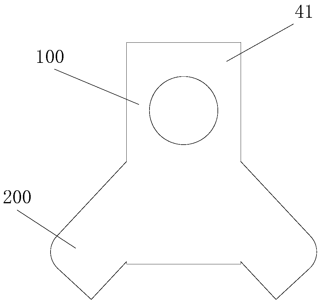
[0039] Figure 1 to Figure 6 Shows the self-locking pull rod provided by the first embodiment of the present invention, which includes an outer tube 1 and an inner tube 2 sleeved in the outer tube 1. The outer tube 1 is fixed, the inner tube 2 moves up and down, and the side of the outer tube 1 is provided There are a number of lock holes 11 for the outer tube restraint buckle, and the outer tube restraint lock holes 11 can be arranged on any side of the outer tube. For the convenience of description, in this embodiment, the outer tube stop buckle lock hole 11 is provided on the right side of the outer tube 1 as an example. A stop buckle 41 is fixed at the bottom of the inner tube 2. The lower part of the stop buckle 41 is heavier than the upper part. The stop buckle 41 includes a fixing part 100 at the upper part and a lower hook on the same side as the lock hole 11 of the outer tube. The boss 200, the fixing part 100 is provided with a through hole, the stop button 41 is inst...
Embodiment 2
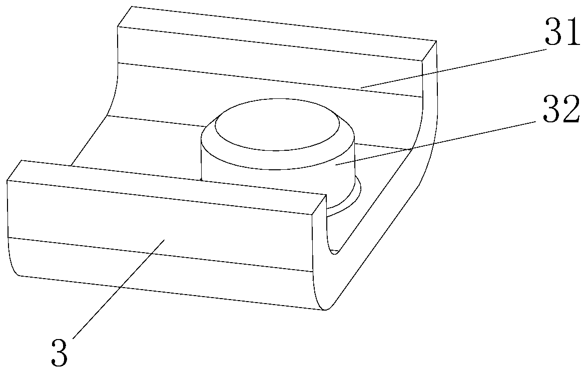
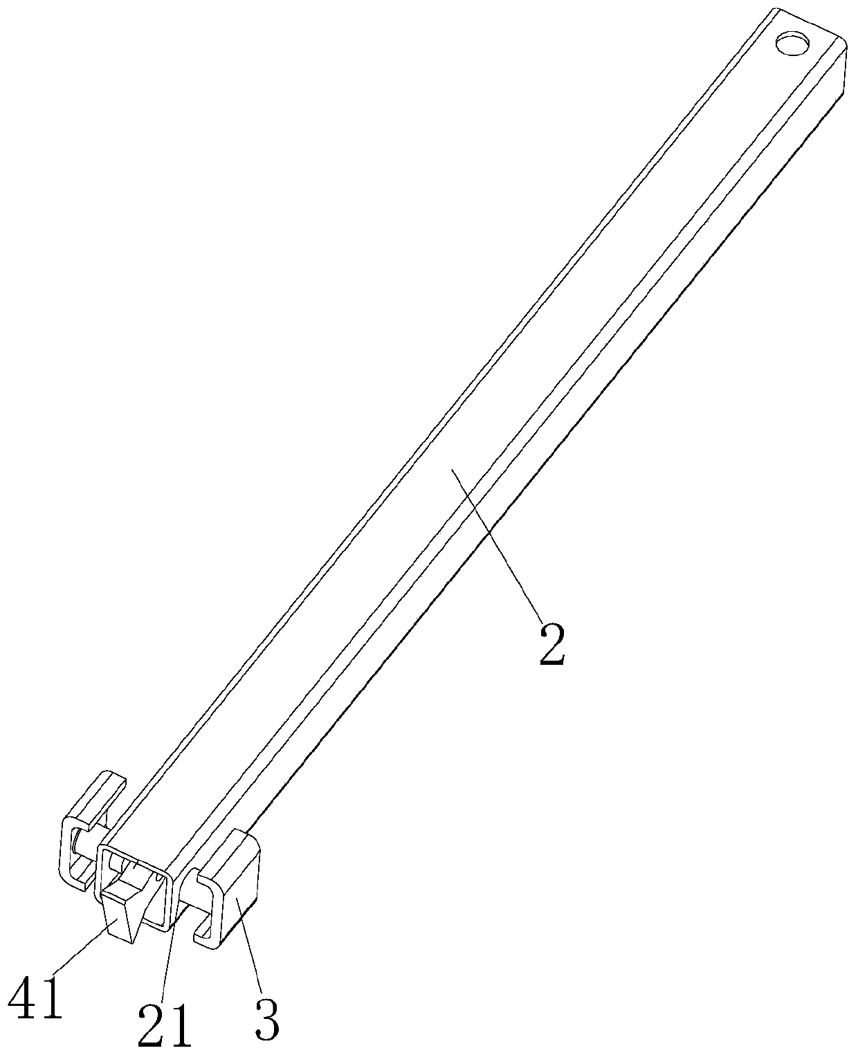
[0042] Figure 7 to Figure 11 The second embodiment of the self-locking pull rod of the present invention is shown. In this embodiment, the fixing member 3 includes a buckle portion 31 on both sides and a convex point 32 in the middle. A structural member mounting hole is provided on the side wall of the inner tube 2 21. The buckle portion 31 is clamped on the outer wall of the inner tube 2; the tie rod also includes a structural member 4, which includes a structural member body 42 located at the lower part and a connecting portion 43 located at the upper part; the structural member body 42 is a hollow structure, and A stop 44 is opened on the same side of the outer tube stop buckle lock hole 11, and the stop buckle 41 is installed in the structure body 42 through the through hole through the mounting shaft 45, and can swing left and right in the space of the structure body 42; A mounting hole 46 is opened in the middle of the portion 43, which is on the same side as the structu...
Embodiment 3
[0045] Both the first embodiment and the second embodiment of the self-locking pull rod of the present invention can realize the self-locking function when the pull rod is inclined. It cannot be self-locked when the pull rod is in a vertical state. Therefore, it is designed that the pull rod can also be in a vertical state. The third embodiment of self-locking, such as Figure 12 to Figure 16 As shown, in this embodiment, the fixing portion 100 of the retractable buckle 41 is also provided with a trigger portion 300 on the side opposite to the outer tube retractable buckle lock hole 11, and the outer pipe 1 is provided with a protrusion on the same side as the trigger portion 300. Touch point 5. The stop buckle 41 in this embodiment can be used alone or in combination with the structural member 4. When used alone, the stop buckle in the first embodiment can be replaced with a stop buckle with a trigger portion 300. When the structural member 4 is used in conjunction, it is nec...
PUM
 Abstract
Description
Claims
Application Information
 - R&D
- Intellectual Property
- Life Sciences
- Materials
- Tech Scout
- Unparalleled Data Quality
- Higher Quality Content
- 60% Fewer Hallucinations
Browse by: Latest US Patents, China's latest patents, Technical Efficacy Thesaurus, Application Domain, Technology Topic, Popular Technical Reports.
© 2025 PatSnap. All rights reserved.Legal|Privacy policy|Modern Slavery Act Transparency Statement|Sitemap|About US| Contact US: help@patsnap.com