A lifting charging pile

A charging pile and lift-type technology, applied in the field of lift-type charging piles, can solve the problems of time-consuming and laborious maintenance, blocking the water inlet or outlet of the rainwater collector, being easily injured and pedestrians, etc., and achieving the effect of easy maintenance.

A charging pile and lift-type technology, applied in the field of lift-type charging piles, can solve the problems of time-consuming and laborious maintenance, blocking the water inlet or outlet of the rainwater collector, being easily injured and pedestrians, etc., and achieving the effect of easy maintenance.

CN110936838BActive Publication Date: 2022-01-14ANHUI KECHUANG NEWENERGY TECH CO LTD

Image

  • A lifting charging pile
  • A lifting charging pile
  • A lifting charging pile

Examples


Embodiment Construction

[0020] In order to make the object, technical solution and advantages of the present invention clearer, the present invention will be described in further detail below in conjunction with specific embodiments and with reference to the accompanying drawings.

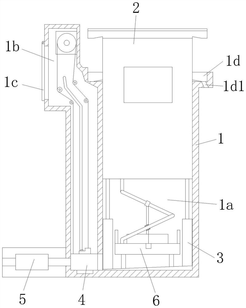
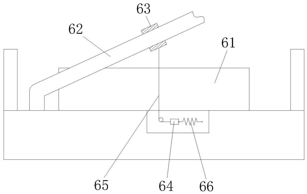
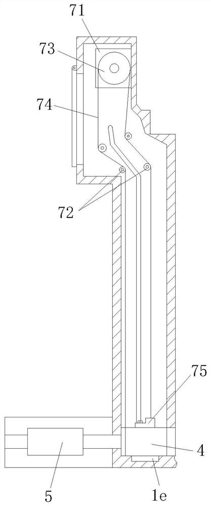
[0021] As an embodiment, the present invention provides a lifting charging pile, including an embedded part and a charging pile body, one side of the embedded part has a receiving cavity, and the other side of the embedded part has an auxiliary cavity, so A vertical sliding groove is installed in the accommodating chamber, the charging pile body is slidably installed in the sliding groove, and a hydraulic cylinder is installed on the lower part of the charging pile body, and the output end of the hydraulic cylinder is connected to the charging pile body. connected, the auxiliary cavity is equipped with a guide groove arranged vertically, the guide groove is equipped with a slidable filter assembly, the lower part of the au...


PUM


Abstract

The invention discloses a lifting type charging pile, which comprises an embedded part and a charging pile body. One side of the embedded part has an accommodation cavity, and the other side of the embedded part has an auxiliary cavity. A sliding groove is installed in the accommodation cavity for charging. The pile body is slidably installed in the sliding groove, the lower part of the charging pile body is equipped with a hydraulic cylinder, the auxiliary chamber is equipped with a guide groove, the guide groove is equipped with a filter assembly, the lower part of the auxiliary chamber is equipped with a pump, and the auxiliary chamber is installed. A moving component is provided, and a drain is provided in the accommodating chamber. The present invention realizes the structural design of the hidden charging pile through the cooperation of the embedded parts and the charging pile body. At the same time, the cooperation between the filter assembly and the pump is arranged in the embedded parts, so that the rainwater flowing into the embedded parts can be pumped out, and The mobile component can drive the filter component to move, which is convenient for the maintenance of the mobile component.

Description

technical field [0001] The invention relates to the field of lifting charging piles, in particular to a lifting charging pile. Background technique [0002] The car charging pile can realize timing, electricity meter, and amount charging, and it can be used as a charging terminal for cars. In order to solve the problem that the existing charging piles are often exposed and easily hurt pedestrians once leakage occurs, a Chinese patent discloses a hidden charging pile (application number is CN201721006835.3). The charging pile structure includes a charging room, a charging Pile, charging gun, cover plate, water tank and rainwater collector; the charging room is installed underground, a motor is installed at the bottom of the charging room, the shaft end of the motor is fixedly connected to a rotating shaft, and the top of the rotating shaft is fixedly connected to a cover plate. The interior of the charging chamber is provided with a partition, the bottom of the charging cham...

Claims


Application Information

Patent Timeline
14 Jan 2022
Publication
CN110936838B
IPC
B60L53/31; B01D29/01; B01D29/56; B01D29/96
CPC
B60L53/31; B01D29/01; B01D29/56; B01D29/96; Y02T10/70; Y02T10/7072; Y02T90/12
Inventors
各阿杰