Feeding device of production line

A production line and raw material technology, applied in the field of production line feeding devices, can solve problems such as low degree of mechanization, and achieve the effects of convenient operation, improved production work efficiency, and convenient grasping and releasing.

Inactive Publication Date: 2020-03-31
HUNAN JINGZHENG EQUIP MFG
View PDF0 Cites 4 Cited by
  • Summary
  • Abstract
  • Description
  • Claims
  • Application Information

AI Technical Summary

Problems solved by technology

[0002] At present, the degree of mechanization of domestic flooring production enterprises is generally low, and repetitive mechanical labor such as palletizing and loading is still basically done manually

Method used


Image

  • Feeding device of production line
  • Feeding device of production line

Examples


Embodiment 1

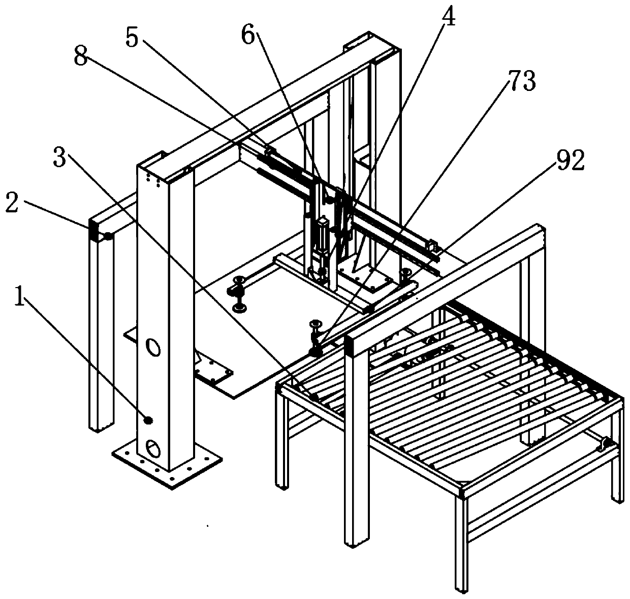
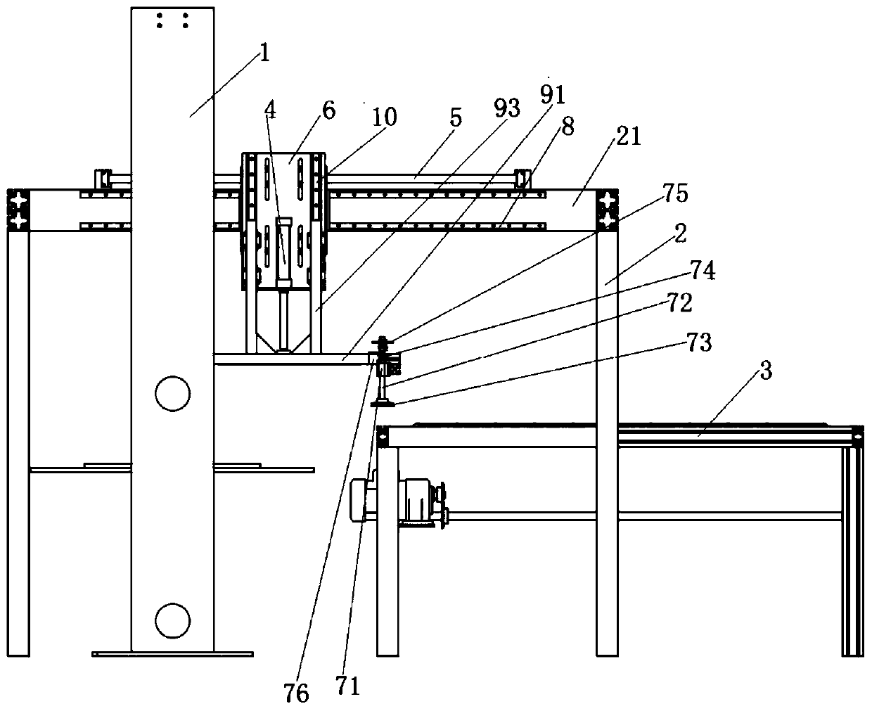
[0023] combine figure 1 and figure 2 , a production line feeding device of this embodiment, including a feeding manipulator and a hydraulic lifting platform 1 that can ensure that the height of the material can be lifted back to the original position after grabbing a piece of raw material, greatly reducing the manipulator's grabbing stroke and reducing the grabbing time , to improve production efficiency; the rear of the hydraulic lifting platform 1 is provided with a stick conveyor 3; the feeding manipulator includes a support frame 2, and the support frame 2 is composed of a beam 21 arranged in the front and rear directions and legs fixed at both ends of the beam 21. One of the legs is located in front of the hydraulic lift 1, and the other leg is located in the middle of the stick conveyor 3; the top surface of the crossbeam 21 is fixedly equipped with a rodless cylinder 5, and the cylinder slider of the rodless cylinder 5 is fixedly installed with a Plate 6, the mounting...

Embodiment 2

[0026] The basic structure of a production line feeding device of this embodiment is the same as that of Embodiment 1, the difference is that: a travel switch 76 is arranged on the position of the longitudinal arm beam 92 facing the pressure plate 75, and the distance between the travel switch 76 and the pressure plate 75 The distance is greater than the drop height of the pressure plate 75 when the vacuum suction cup 73 grabs one piece of raw material, and is smaller than the drop height of the pressure plate 75 when the vacuum suction cup 73 grabs two raw materials, so as to ensure that the manipulator grabs one piece of raw material at a time, and avoids the fact that the manipulator grabs multiple plates at a time. Then affect the normal work of the follow-up process during automatic production.

[0027] After the vacuum suction cup 73 grabs a piece of raw material, the gravity of the raw material drives the optical axis 72 to descend, and at the same time the spring 74 is ...


PUM


Abstract

The invention discloses a feeding device of a production line. The feeding device comprises a feeding manipulator and a hydraulic lifting table capable of ensuring that the height of a material can belifted back to the original position after the material is grabbed every time, wherein a roller conveyor is arranged behind the hydraulic lifting table; the feeding manipulator comprises a supportingframe; the supporting frame is composed of a cross beam arranged in the front-back direction and supporting legs fixedly arranged at the two ends of the cross beam; the supporting legs are positionedon the front side and the rear side of the hydraulic lifting table; a rodless air cylinder is fixedly mounted on the top surface of the cross beam; an mounting plate is fixedly mounted on an air cylinder sliding block of the rodless air cylinder; a lifting air cylinder is vertically mounted on the mounting plate; and a manipulator is mounted at the tail end of a telescopic rod of the lifting aircylinder. The feeding device is simple in structure, convenient to operate and low in manufacturing and maintenance cost, the feeding interval time is greatly shortened, meanwhile, the manipulator grabs one piece of raw material at a time, and the situation that the normal work of subsequent procedures during automatic production is influenced due to the fact that the manipulator grabs a pluralityof plates at a time is avoided.

Description

technical field [0001] The invention relates to a feeding device, more specifically, to a feeding device for a production line. Background technique [0002] At present, the degree of mechanization of domestic flooring production enterprises is generally low, and repetitive mechanical labor such as palletizing and loading is basically still done manually. With the rise of labor costs and the gradual reduction of low-end labor force, the pressure on enterprises is increasing day by day. In the existing floor production, the size of the material transported by the manipulator is large, but the speed of transport is required to be high. Contents of the invention [0003] 1. The technical problem to be solved by the invention [0004] The purpose of the present invention is to overcome the shortcomings of the slow handling speed of existing manipulators and provide a feeding device for a production line. Adopting the technical solution of the present invention, the structure...

Claims


Application Information

Patent Timeline
Patent Type & Authority Applications(China)
IPC IPC(8): B65G47/91
CPCB65G47/912
Inventor 肖双华
Owner HUNAN JINGZHENG EQUIP MFG
Why Eureka
Try Eureka