
Paper disc frame with active discharging function
A paper tray rack and functional technology, applied in the field of paper tray racks, can solve problems such as out-of-control feeding speed, and achieve the effect of accurate control
- Summary
- Abstract
- Description
- Claims
- Application Information
AI Technical Summary
Problems solved by technology
Method used
Image

Examples
Embodiment Construction
[0023] The technical solutions of the present invention will be clearly and completely described below in conjunction with specific embodiments. Apparently, the described embodiments are only some of the embodiments of the present invention, not all of them. Based on the embodiments of the present invention, all other embodiments obtained by persons of ordinary skill in the art without creative efforts fall within the protection scope of the present invention.
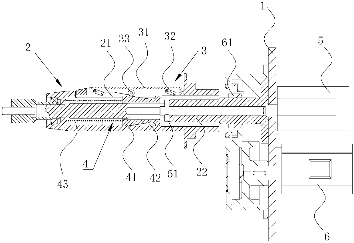
[0024] A paper tray rack with active discharging function, refer to figure 1 , including a vertically arranged wallboard 1, one side of the wallboard 1 is rotatably connected with a support shaft 2, and the support shaft 2 is perpendicular to the end surface of the wallboard 1. In the side wall of the support shaft 2, along its axial direction, a connecting rod cavity 21 is opened to communicate with the outside world. In this embodiment, three connecting rod cavities 21 are evenly opened along the circumferential dir...
PUM
 Abstract
Description
Claims
Application Information