Heat efficiency lifting method for filling-storing type liquid filling rate-variable heat pipe and device

A technology of variable liquid filling rate and heat pipe device, which is applied in indirect heat exchangers, lighting and heating equipment, etc., can solve the problems of inability to adjust the working conditions throughout the year, difficult control, complicated operation, etc., and achieves a broad market application prospect, Change the liquid filling rate, and the effect of energy saving is remarkable

Active Publication Date: 2020-03-31
DONGHUA UNIV
View PDF5 Cites 1 Cited by
  • Summary
  • Abstract
  • Description
  • Claims
  • Application Information

AI Technical Summary

Problems solved by technology

Existing heat pipe products cannot be adjusted accordingly for the annual working conditions after the working fluid is charged
Another variable heat conduction heat pipe uses non-condensable gas to change the effective volume and heat exchange area of ​​the heat pipe to adjust the heat conduction performance to keep the temperature of the hot end constant. During use, the charge amount remains unchanged, but the operation is complicated and the control is difficult. Big

Method used


Image

  • Heat efficiency lifting method for filling-storing type liquid filling rate-variable heat pipe and device
  • Heat efficiency lifting method for filling-storing type liquid filling rate-variable heat pipe and device
  • Heat efficiency lifting method for filling-storing type liquid filling rate-variable heat pipe and device

Examples


Embodiment Construction

[0021] Below in conjunction with specific embodiment, further illustrate the present invention. It should be understood that these examples are only used to illustrate the present invention and are not intended to limit the scope of the present invention. In addition, it should be understood that after reading the teachings of the present invention, those skilled in the art can make various changes or modifications to the present invention, and these equivalent forms also fall within the scope defined by the appended claims of the present application.

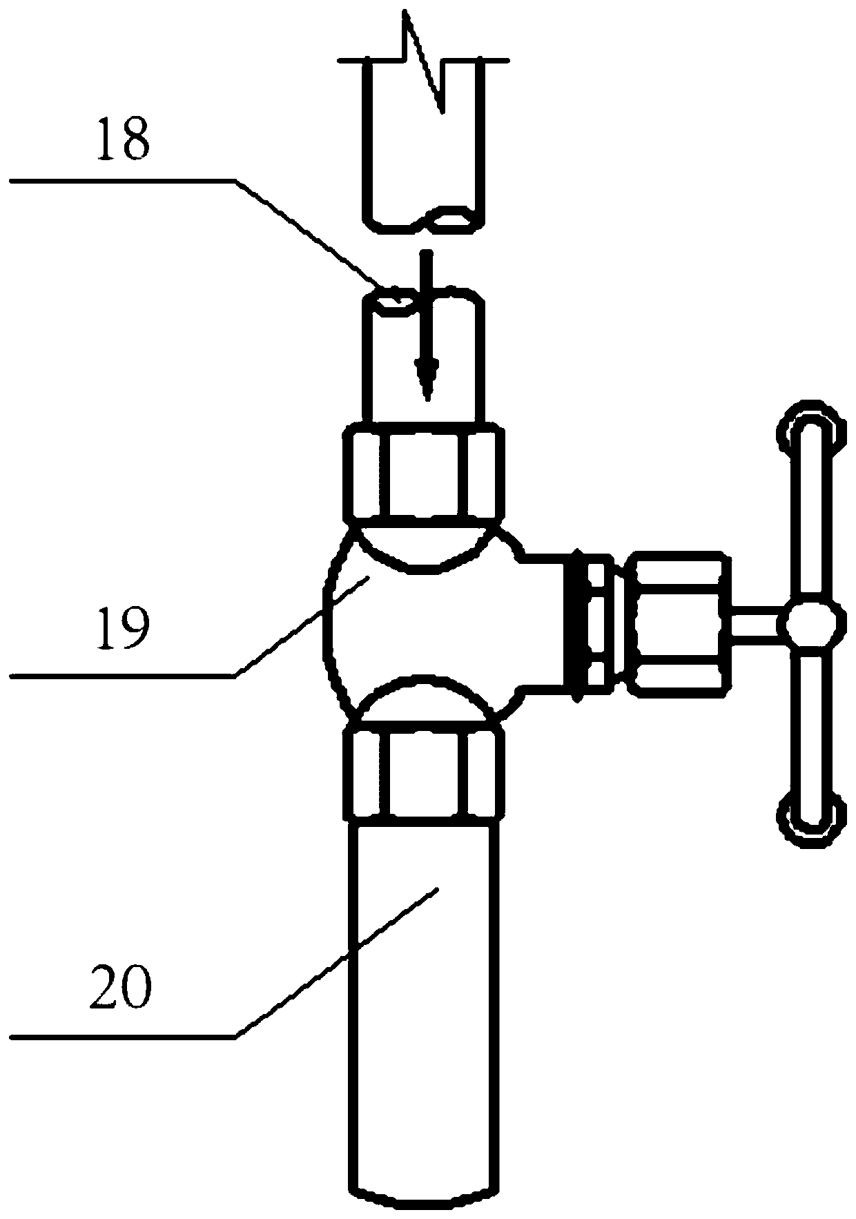
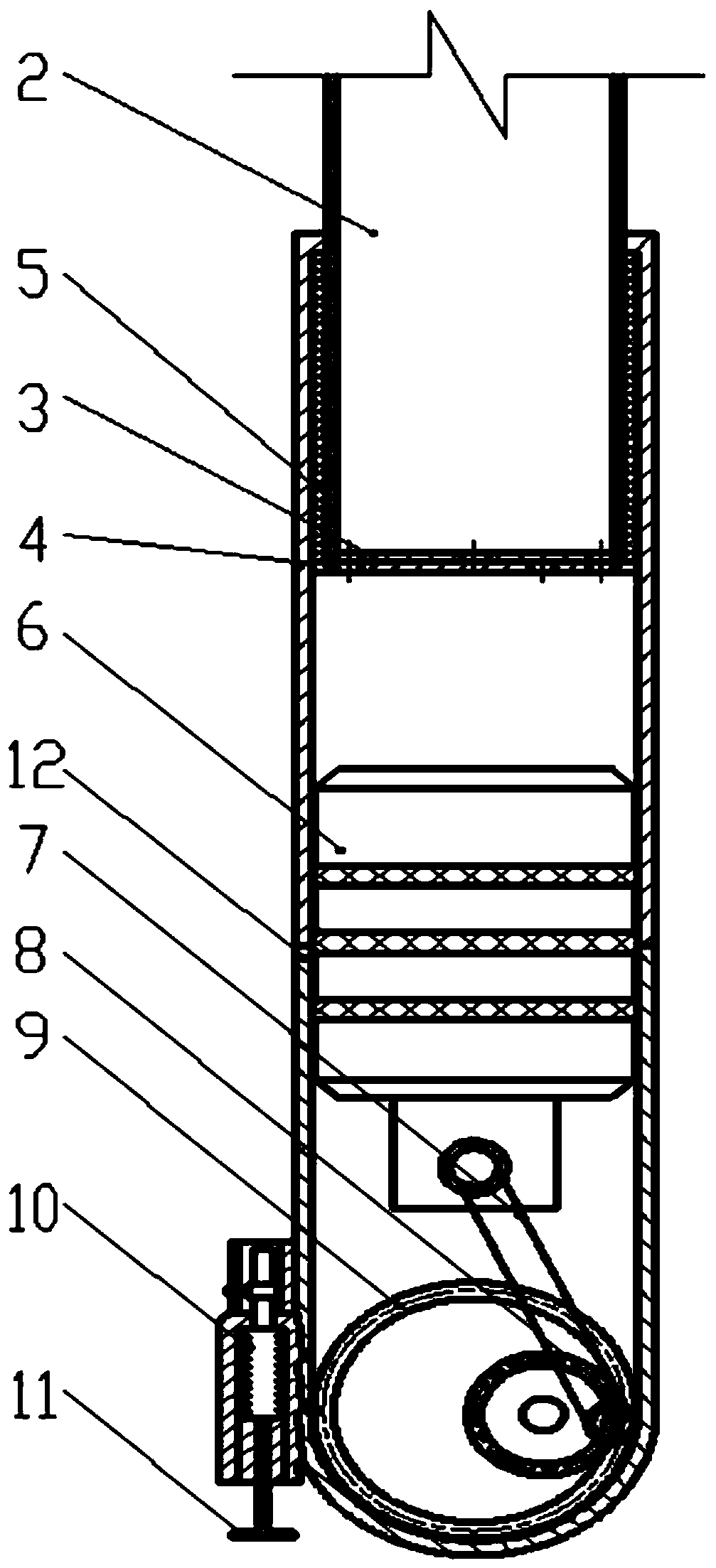
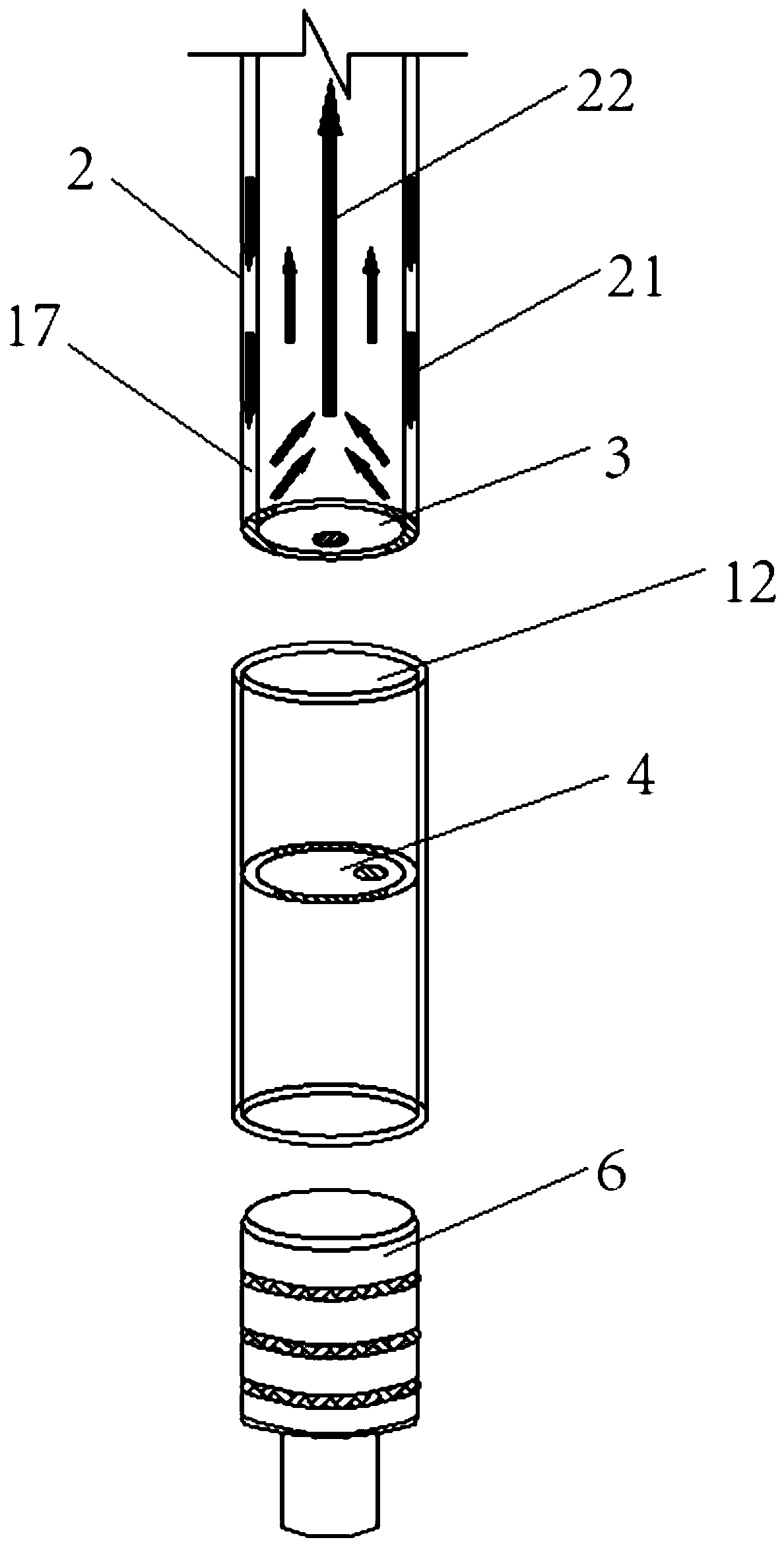
[0022] like figure 1 As shown, the present invention discloses a method for improving thermal efficiency of a rechargeable heat pipe with variable liquid filling rate, including all methods for improving the thermal efficiency of the heat pipe by adjusting the liquid filling rate by changing the flow rate of the working substance. The method of improving the thermal efficiency of the heat pipe by adjusting the liquid filling r...


PUM


Abstract

The invention provides a heat efficiency lifting method for a filling-storing type liquid filling rate-variable heat pipe. The heat efficiency lifting method is characterized in that the liquid filling rate of the heat pipe is adjusted by changing the flowing amount of a working medium in the heat pipe, and the purpose of improving the heat efficiency of the heat pipe is achieved. The invention further provides a liquid filling rate-variable heat pipe device in another technical scheme. According to the liquid filling rate-variable heat pipe device, under the condition that an inner cavity structure, the use volume, the heat exchange area and the working medium composition of an original heat pipe are unchanged, the filling amount inside the heat pipe is changed through the mode by which the working medium of the heat pipe is recovered in a working medium storage device in a liquid state and reused, so that the liquid filling rate is changed, the working medium is taken and dischargedconveniently, fast and adjustably so as to adapt to various working conditions in real time, the energy-saving benefit is remarkable, and a wide market application prospect is achieved.

Description

technical field [0001] The invention relates to a technical method and a device for improving the thermal efficiency of a heat pipe, and belongs to the technical field of engineering energy. Background technique [0002] In the contemporary social environment, the problem of energy depletion has seriously hindered the rapid development of the economy and society. As a highly efficient element for enhanced heat transfer, heat pipes are widely used in high-end electronic equipment, HVAC, power, metallurgy, glass, chemical industry, light industry , ceramics and other fields. Under certain working conditions, the liquid filling rate of the heat pipe has a significant impact on the thermal efficiency. Existing heat pipe products cannot make corresponding adjustments to the annual working conditions after the working medium is charged. Another variable heat conduction heat pipe uses non-condensable gas to change the effective volume and heat exchange area of ​​the heat pipe to ...

Claims


Application Information

Patent Timeline
IPC IPC(8): F28D15/02
CPCF28D15/02F28D15/0283
Inventor 刘刚洪旸冯怡苇严浩甘长德宋德龙解紫茹
Owner DONGHUA UNIV
Why Eureka
Try Eureka