
Engine cooling fan speed regulating device

A technology of engine cooling and speed regulating device, which is applied in the direction of engine cooling, transmission, engine components, etc., can solve the problems of less use, poor precision, large size, etc., achieve simple structure, improve corresponding speed and accuracy, and small size Effect

Inactive Publication Date: 2020-12-11
BEIJING INSTITUTE OF TECHNOLOGYGY
View PDF7 Cites 2 Cited by
  • Summary
  • Abstract
  • Description
  • Claims
  • Application Information

AI Technical Summary

Problems solved by technology

The outlet-adjustable hydraulic coupler controls the change of the liquid filling rate through the spoon tube mechanism. The speed regulating device is sensitive and has high precision. It is often used to control the speed of fans and water pumps. Difficult for small car engines
The inlet adjustable hydraulic coupler uses a throttle valve to control the flow of working oil, and then controls the fluid filling rate of the hydraulic coupler. The speed regulating device has a simple structure and takes up less space, but it also has the characteristics of slow response and poor precision. , so use less

Method used


Image

  • Engine cooling fan speed regulating device
  • Engine cooling fan speed regulating device
  • Engine cooling fan speed regulating device

Examples


Embodiment Construction

[0038] In order to more clearly understand the above objects, features and advantages of the present invention, the present invention will be further described in detail below in conjunction with the accompanying drawings and embodiments. It should be understood that the described embodiments are some, not all, embodiments of the present invention. The following examples are only used to explain the present invention, but not to limit the present invention. All other embodiments obtained by those skilled in the art based on the described embodiments of the present invention belong to the protection scope of the present invention. Unless otherwise specified, the technical means used in the embodiments are conventional means or existing technologies well known to those skilled in the art.

[0039] It should be noted that in this article, relative terms such as "first" and "second" are only used to distinguish one entity or operation from another entity or operation, and do not ...


PUM


Abstract

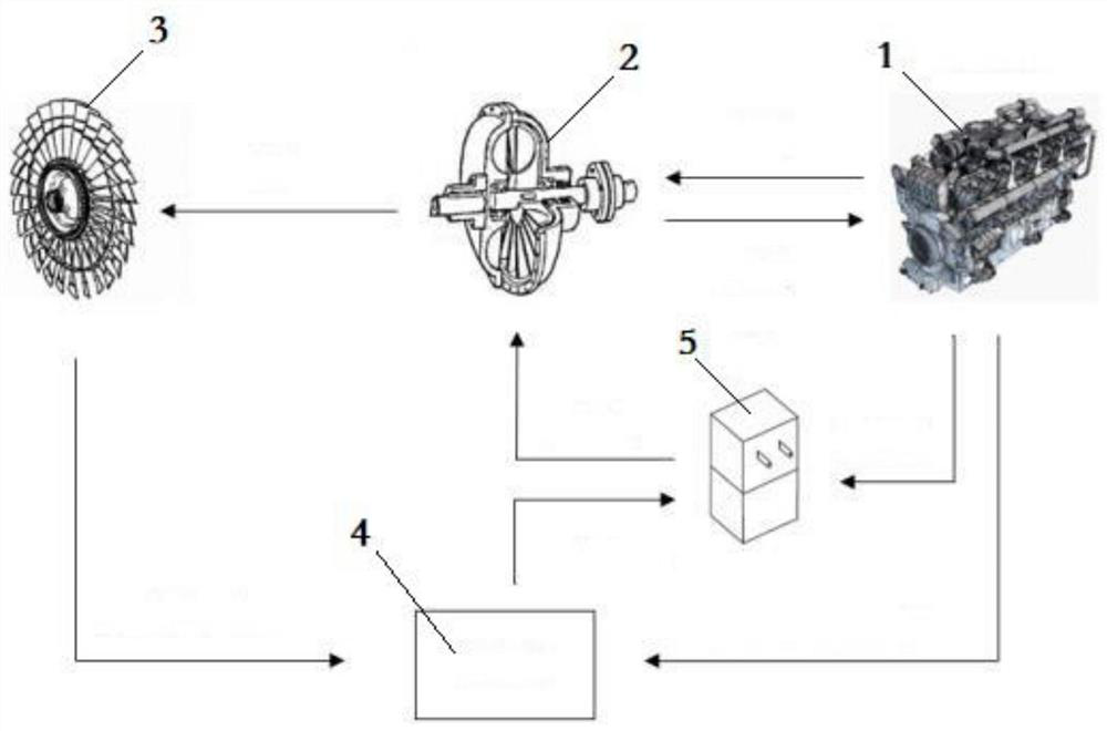
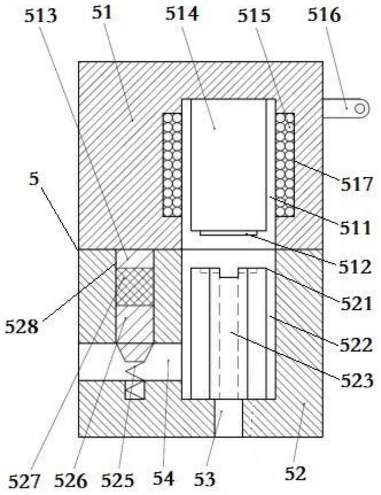
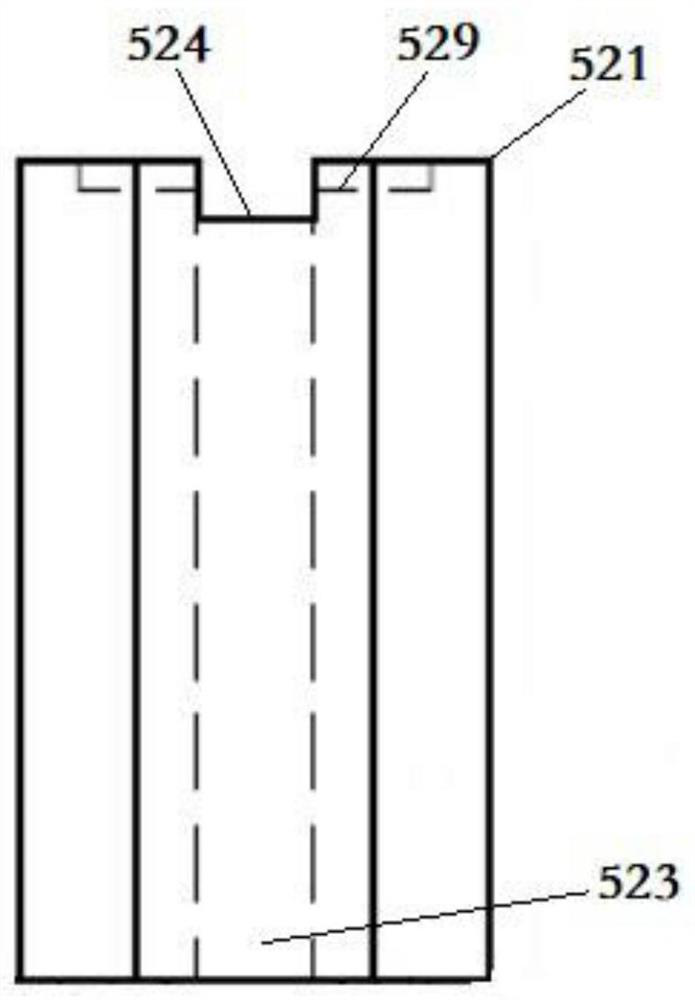
The invention relates to the technical field of engine cooling, and provides an engine cooling fan speed regulating device. The engine cooling fan speed regulating device comprises an engine unit, theengine unit is connected with a coupling unit, the coupling unit is connected with a fan unit, and the engine unit and the coupling unit are respectively electrically connected with an electromagnetic valve unit; the engine unit, the fan unit and the electromagnetic valve unit are in communication connection with a control unit, the control unit is further provided with a rotating speed sensor and a temperature sensor; and the electromagnetic valve unit comprises a first valve body, and the first valve body is connected with a second valve body; By adopting the technical scheme of the invention, the rotating speed sensor and the temperature sensor output collected signals to the electromagnetic valve unit, the electromagnetic valve unit changes the time of each opening and closing actionaccording to the input signals, the rotating speed of the fan unit is controlled and adjusted in real time, the corresponding speed and precision of the coupling unit are improved, the structure is simple, the size is small and the engine cooling fan speed regulating device is suitable for vehicle engines with narrow spaces.

Description

technical field [0001] The invention relates to the technical field of engine cooling, in particular to an engine cooling fan speed regulating device. Background technique [0002] Regarding the automatic control of the engine cooling fan, most of the motors are used in the prior art to adjust the speed and adjust the speed of the silicon oil clutch. However, the introduction of the motor also brings a series of problems such as the selection of the motor and the complicated structure of the device. However, the silicon oil clutch speed control method cannot continuously adjust the fan speed, that is to say, in the silicon oil clutch speed control method, the fan speed can only be adjusted step by step step by step, which cannot accurately provide the best cooling intensity under this working condition. In addition, inspired by the application of speed-regulating hydraulic couplings in fans and water pumps, people began to try and study the use of speed-regulating hydraulic...

Claims


Application Information

Patent Timeline
Patent Type & Authority Applications(China)
IPC IPC(8): F01P7/02F01P7/04F16H41/04F16H41/24F16K31/06
CPCF01P7/026F01P7/042F16H41/04F16H41/24F16K31/06
Inventor 张付军王尚炎崔涛张禄兴赵长禄
Owner BEIJING INSTITUTE OF TECHNOLOGYGY
Learn More